Deceleration clutch device and washing machine

A technology of clutch device and clutch flower, which is applied in the field of washing machines, can solve the problems of slow sliding down of the clutch shaft sleeve, blockage of the clutch sleeve, slow sliding speed, etc., and achieve faster separation and approach speed and faster up and down sliding Speed, frictional noise reduction effect

Active Publication Date: 2017-09-08
QINGDAO HAIER WASHING MASCH CO LTD +1
View PDF2 Cites 6 Cited by
  • Summary
  • Abstract
  • Description
  • Claims
  • Application Information

AI Technical Summary

Problems solved by technology

[0004] Since the shift fork moves up and down by rotating around the shaft, when the shift fork pushes the positioning protrusion upward, the shift fork slides from one side of the positioning protrusion to the other side of the positioning protrusion. In the above process, the shift fork and the positioning protrusion The large sliding friction between the positioning protrusions causes the sliding speed of the shift fork to be slower, the speed of the clutch sleeve to slide upwards is slower, the speed of separation of the input sleeve and the rotor is slower, and in the washing machine, it will cause the rotation time of the washing tub Longer, affecting the use of the washing machine
On the contrary, when the shift fork no longer pushes up the positioning protrusion, the shift fork returns to the initial position. In the above process, the sliding friction between the shift fork and the positioning protrusion is large, resulting in a slow sliding speed of the shift fork, and the clutch The sliding speed of the shaft sleeve is slow, and the speed of the input shaft sleeve and the rotor is relatively slow. In the washing machine, the rotation time of the washing tub will be shortened, which will affect the dehydration effect of the clothes, and may also cause the blockage of the clutch sleeve. washing machine not working properly

Method used


Image

  • Deceleration clutch device and washing machine
  • Deceleration clutch device and washing machine
  • Deceleration clutch device and washing machine

Examples


Embodiment 1

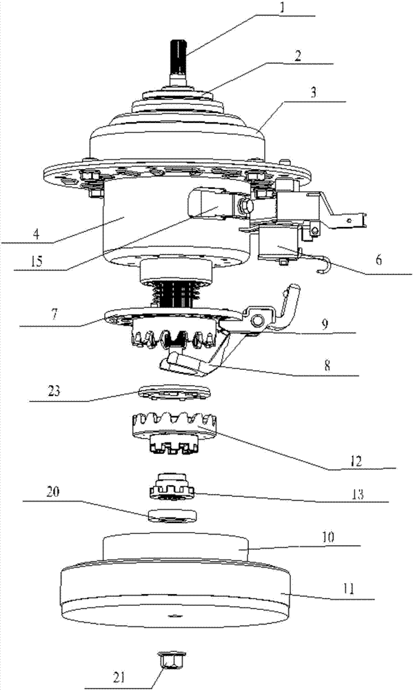
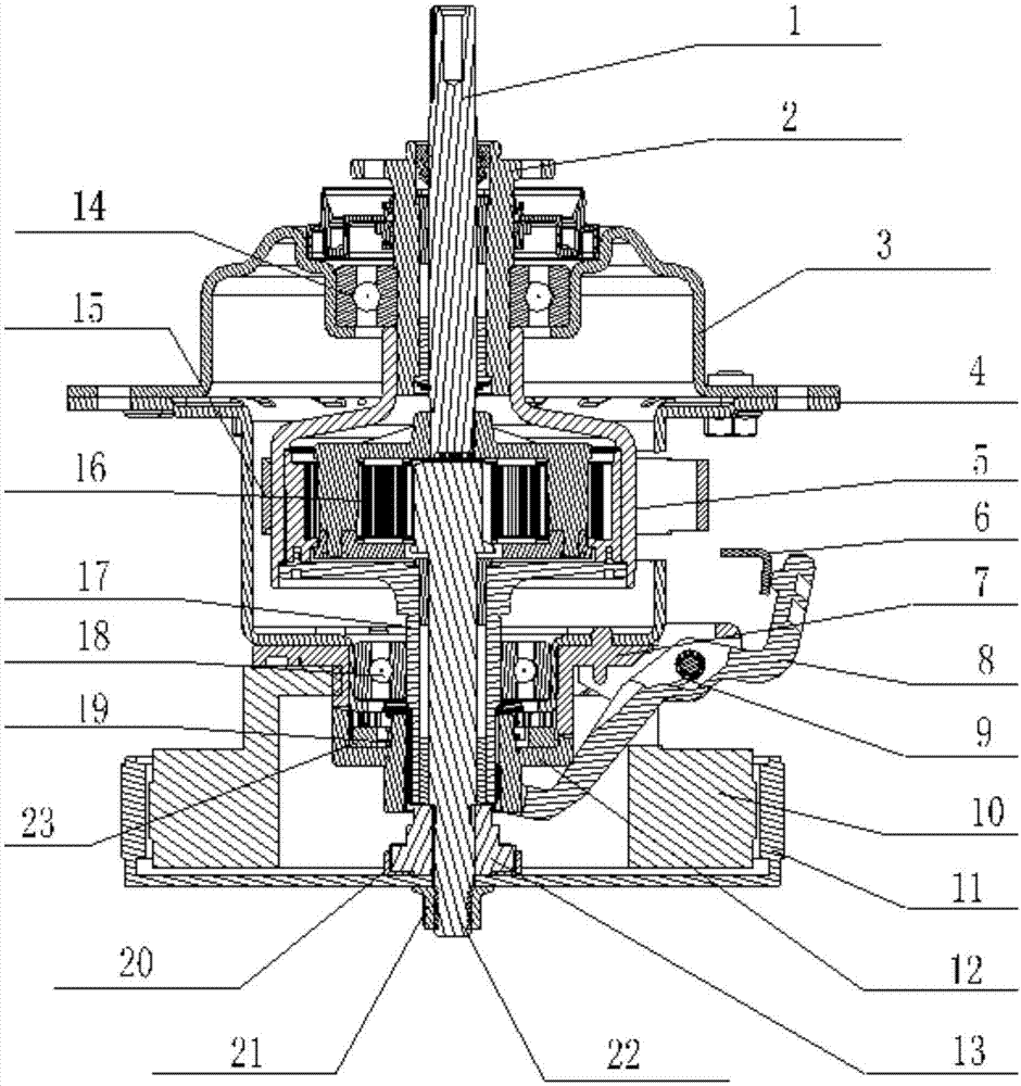
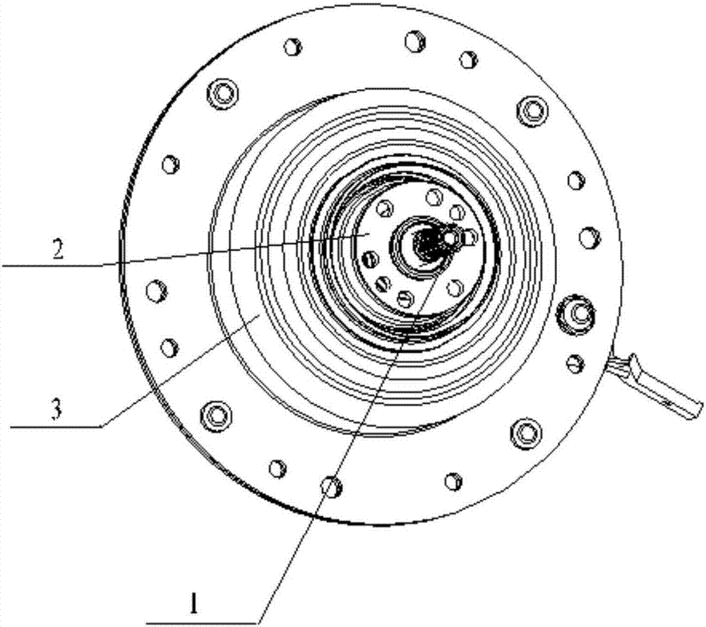
[0053] Such as Figure 1-26 As shown, in this embodiment, the input shaft 22 is sleeved with a torque bushing 13, the torque bushing 13 cannot rotate axially relative to the input shaft 22, and the torque bushing 13 and the clutch bushing 12 To realize the connection between the clutch bushing 12 and the rotor 11, the lower part of the torque bushing 13 is connected with the rotor 11. Preferably, a first damping pad 20 is provided between the lower part of the torque bushing 13 and the rotor 11 , to reduce the noise generated by the rotor 11 during rotation and the impact on the reduction clutch device.

[0054] The inner wall of the torque bushing 13 is provided with a second internal spline 36 to realize the meshing connection between the torque bushing 13 and the input shaft 22, so that the torque bushing 13 rotates with the rotation of the input shaft 22 and rotates The top of the torque shaft sleeve 13 is provided with a first external spline 38, and the bottom of the cl...

Embodiment 2

[0057] Such as Figure 1-26 As shown, in this embodiment, a housing 31 consisting of an upper end housing 3 and a lower end housing 4 is provided above the clutch shaft sleeve 12, a fixing bracket 7 is provided on the housing 31, and the outer periphery of the positioning protrusion 29 is provided with The positioning wall 30 extending upwards, after the clutch sleeve 12 slides upwards, the positioning wall 30 is connected with the fixed bracket 7, specifically, the lower part of the fixed bracket 7 is provided with a positioning spline 37, and the upper part of the positioning wall 30 is provided with a corresponding The second clutch spline 32, to realize the engagement connection of the two, in the washing machine, to prevent the washing tub from rotating during washing. Wherein, the tooth profile end of the positioning spline 37 is designed as a small circular arc, the angle between the left side of the tooth profile and the vertical plane is 0°-10°, and the angle between ...

Embodiment 3

[0063] Such as Figure 1-26 As shown, in this embodiment, the oil inlet end of the oil leakage hole 26 is set outside the oil storage tank 25 and is set close to the outside of the positioning protrusion 29 .

[0064] The above arrangement prevents the lubricating grease in the oil storage tank 25 from being thrown out of the oil storage tank 25 when the clutch sleeve 12 rotates.

[0065] The specification of the oil leakage hole 26 is smaller than that of the oil storage tank 25 , so that the lubricating grease slowly flows to the contact surface between the positioning protrusion 29 and the shift fork 8 .

[0066] A plurality of oil storage tanks 25 are evenly distributed on the positioning protrusion 29;

[0067] Preferably, the oil leakage hole 26 is a through hole with a circular cross section.

[0068] The second damping pad 23 is sandwiched between the positioning protrusion 29 and the housing 31 to reduce the contact noise between the positioning wall 30 and the hous...


PUM


Abstract

The invention relates to a deceleration clutch device. The deceleration clutch device comprises a shell, a clutch shaft sleeve and a shifting fork, wherein the upper portion of the clutch shaft sleeve is connected with the shell, and the shifting fork makes contact with the clutch shaft sleeve. Relative motion exists between the shifting fork and the clutch shaft sleeve, and lubricating grease is arranged on the surface where the shifting fork makes contact with the clutch shaft sleeve so as to reduce the sliding friction force between the shifting fork and the clutch shaft sleeve. The invention further relates to a washing machine. The washing machine is provided with the deceleration clutch device. The lubricating grease is arranged on the surface where a positioning flange makes contact with the shifting fork so as to reduce the sliding friction force between the positioning flange and the shifting fork, the sliding speed of the shifting fork is increased, the up-down sliding speed of the clutch shaft sleeve is increased, the speed at which a dewatering shaft is separated from a rotor and the speed at which the dewatering shaft is approached to the rotor are increased, the difference between the rotating time and the set time of a washing barrel is reduced, the frictional abnormal noise is reduced, the reliable performance of a clutch is improved, and the user experience effect is improved.

Description

technical field [0001] The invention relates to the field of washing machines, in particular to a deceleration clutch device. Background technique [0002] The existing deceleration clutch device includes a frequency conversion motor composed of a rotor and a stator, and an input shaft whose lower part is connected to the rotor through a nut. The outer sleeve of the input shaft is provided with an input shaft sleeve, and an oil-impregnated bearing is arranged between the input shaft and the input shaft sleeve. , so that the input shaft can rotate axially relative to the input shaft sleeve. The outer sleeve of the input shaft sleeve is provided with a clutch sleeve. The clutch sleeve cannot rotate axially relative to the input sleeve, but can slide up and down in the axial direction. The clutch sleeve Sliding down, the clutch bushing is connected with the rotor, the input bushing rotates with the rotation of the clutch bushing, the clutch bushing slides upwards, the clutch bu...

Claims


Application Information

Patent Timeline
Patent Type & Authority Applications(China)
IPC IPC(8): D06F37/40D06F37/20
CPCD06F37/20D06F37/40
Inventor 张刚金田云田云龙庄仲凯周春霞
Owner QINGDAO HAIER WASHING MASCH CO LTD
Why Eureka
Try Eureka