
Agricultural machine transmission gear

A technology for transmission gears and agricultural machinery, which is applied to transmission parts, gear lubrication/cooling, belts/chains/gears, etc., and can solve the problems of being easily entangled by soil, rocks or weeds, hindering, and burning the driving device.

Inactive Publication Date: 2017-09-08
ANHUI AOTAI POWDER METALLURGY
View PDF7 Cites 3 Cited by
  • Summary
  • Abstract
  • Description
  • Claims
  • Application Information

AI Technical Summary

Problems solved by technology

[0002] Agricultural machinery refers to various machinery used in the process of crop planting and animal husbandry production, as well as in the process of primary processing and handling of agricultural and animal products. Agricultural machinery includes agricultural power machinery, farmland construction machinery, soil tillage machinery, planting and Fertilization machinery, plant protection machinery, farmland drainage and irrigation machinery, crop harvesting machinery, agricultural product processing machinery, animal husbandry machinery and agricultural transportation machinery, etc., because agricultural machinery works in the farmland for a long time, it is easily disturbed by soil or other impurities in the farmland Breaking, in the transmission gear of agricultural machinery, it is often exposed to the outside of the agricultural machinery, and it is easy to be entangled by earth, rocks or weeds or hinder its rotation. After a long period of winding, the transmission gear will suffocate and burn the driving device, resulting large economic loss, for this reason we propose a transmission gear for agricultural machinery

Method used


Image

  • Agricultural machine transmission gear
  • Agricultural machine transmission gear
  • Agricultural machine transmission gear

Examples


Embodiment

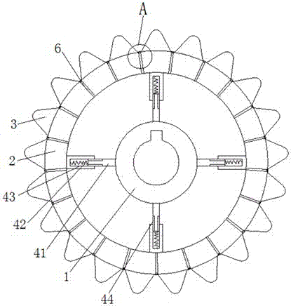
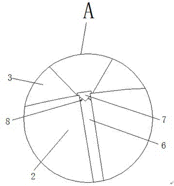
[0019] Embodiment: The device is fixed on the transmission shaft through the fixing hole and the keyway. During the rotation, if sand or small impurities enter the transmission gear, the first fixed ring 1 is driven by the telescopic column 4 to connect with the second fixed ring. 2 A slight displacement occurs, the elastic sleeves on both sides of the extrusion part are squeezed, and the elastic sleeves on the upper and lower sides of the extrusion part slide in the chute, which will squeeze the lubricating oil chamber, and the lubricating oil will squeeze the sealing plug 7, driving The second spring 8 expands and contracts, and the lubricating oil in the lubricating oil chamber is sprayed out from the oil guide hole 6 to clean and lubricate the stuck part of the gear. If the entire transmission gear is blocked, the transmission shaft will drive the first fixed Ring 1 produces positive torque, and second fixed ring 2 produces reverse torque, which will cause the telescopic co...


PUM


Abstract

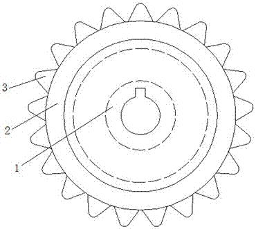
The invention discloses an agricultural machine transmission gear. The agricultural machine transmission gear comprises a first fixing ring, a second fixing ring and gear teeth. An annular groove is formed in the outer wall of the first fixing ring and internally connected with the second fixing ring in a sliding mode, and the second fixing ring extends to the outside the annular groove; the multiple gear teeth arranged in an array mode are arranged on the outer wall of the second fixing ring, four evenly-distributed retractable columns are arranged between the first fixing ring and the second fixing ring and located in the annular groove; and each retractable column comprises a first connecting column body, a first spring and a second connecting column body, one ends of the second connecting column bodies are welded to the inner wall of the second fixing ring, and the other ends of the second connecting column bodies are provided with sliding grooves; and the sliding grooves are slidably connected with the first connecting column bodies, and one ends of the first connecting column bodies are connected with the first springs. According to the agricultural machine transmission gear, the great economic loss which is caused by the fact that a motor is stuck and thus burned away can be prevented, and automatic lubrication can be conducted when the transmission gear is slightly clamped or collided.

Description

technical field [0001] The invention relates to the technical field of agricultural machinery accessories, in particular to a transmission gear for agricultural machinery. Background technique [0002] Agricultural machinery refers to various machinery used in the process of crop planting and animal husbandry production, as well as in the process of primary processing and handling of agricultural and animal products. Agricultural machinery includes agricultural power machinery, farmland construction machinery, soil tillage machinery, planting and Fertilization machinery, plant protection machinery, farmland drainage and irrigation machinery, crop harvesting machinery, agricultural product processing machinery, animal husbandry machinery and agricultural transportation machinery, etc., because agricultural machinery works in the farmland for a long time, it is easily disturbed by soil or other impurities in the farmland Breaking, in the transmission gear of agricultural machi...

Claims


Application Information

Patent Timeline
IPC IPC(8): F16H55/12F16H55/14F16H55/17F16H57/04
CPCF16H55/12F16H55/14F16H55/17F16H57/0467
Inventor 陈田非
Owner ANHUI AOTAI POWDER METALLURGY
Learn More