Resistance-type pressure distribution fabric sensor

A technology of resistive pressure and fabric sensors, which is applied in the measurement of properties and forces of piezoelectric devices, can solve the problems of reducing sensor stability, cumbersome wiring, and long-term heating safety, and achieves improved stability and flexibility. Effects of improving connection stability and simplifying circuit structure

Inactive Publication Date: 2017-09-08
DONGHUA UNIV
View PDF9 Cites 23 Cited by
  • Summary
  • Abstract
  • Description
  • Claims
  • Application Information

AI Technical Summary

Problems solved by technology

Its disadvantage is that the leads in the electrode layer are printed on the surface of the flexible substrate, which is very easy to crack during stretching and deformation, which makes the electrical performance invalid; each electrode needs to be connected to a horizontal lead and a vertical lead respectively, resulting in the overall connection. Too cumbersome and complicated; the electrode layer is pasted or pressed on the surface of the pressure-sensitive material layer. During use, due to the relative sliding friction between the human body and the sensor, there will be shear dislocation between the layers, which will greatly reduce the stability of the sensor.
This structure may have an inaccurate one-to-one correspondence between the response points o

Method used


Image

  • Resistance-type pressure distribution fabric sensor
  • Resistance-type pressure distribution fabric sensor
  • Resistance-type pressure distribution fabric sensor

Examples


Embodiment Construction

[0032] Below in conjunction with specific embodiment, further illustrate the present invention. It should be understood that these examples are only used to illustrate the present invention and are not intended to limit the scope of the present invention. In addition, it should be understood that after reading the teachings of the present invention, those skilled in the art can make various changes or modifications to the present invention, and these equivalent forms also fall within the scope defined by the appended claims of the present application.

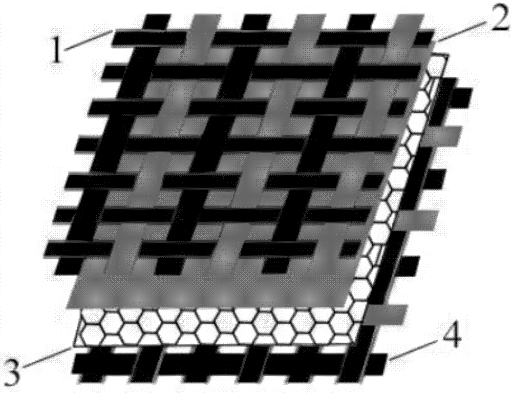
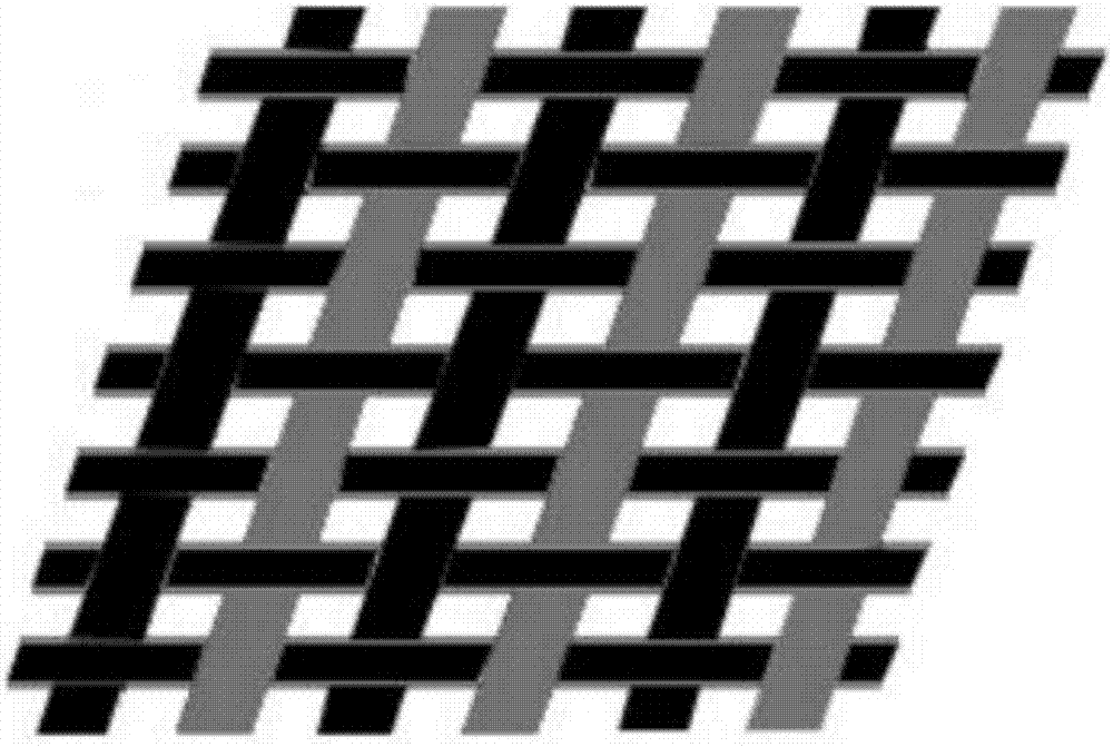
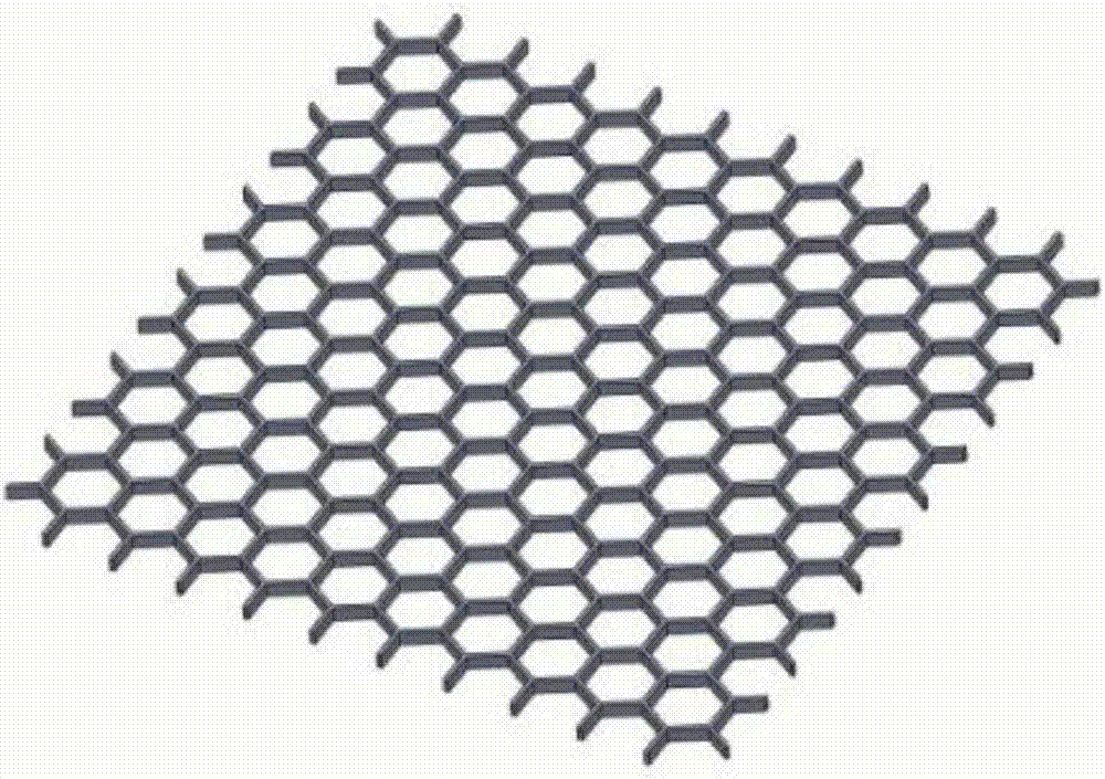
[0033] Embodiments of the present invention relate to a resistive pressure distribution fabric sensor such as figure 1 As shown, it includes an upper electrode layer 1, a conductive layer 2 and a lower electrode layer 4 stacked sequentially from top to bottom; figure 2 As shown, the upper electrode layer 1 and the lower electrode layer 4 are fabrics woven into strips of different widths using conductive yarns and non-conducti...


PUM


Abstract

The present invention relates to a resistance-type pressure distribution fabric sensor. The resistance-type pressure distribution fabric sensor comprises an upper electrode layer, a conductive layer and a lower electrode layer which are laminated orderly from top to bottom, the upper and lower electrode layers are both fabrics formed by knitting the conductive yarns and the non conductive yarns into the stripes of different widths, wherein the stripes formed by the conductive yarns form the electrodes, the stripes formed by the non-conductive yarns form the electrode isolation belts, and the two types of stripes are arranged at intervals. The resistance-type pressure distribution fabric sensor of the present invention can sense the applied pressures and the pressure applying positions, and does not depend on the printed and coated conductive films on the surfaces of the fabrics.

Description

technical field [0001] The invention relates to the technical field of functional textile design, in particular to a resistive pressure distribution fabric sensor. Background technique [0002] With the introduction and rise of the concept of smart home and Internet of Things, smart textiles have become a research hotspot for scholars in recent years, but most of the sensing elements as the core part still use traditional sensors, which are very rigid. The practical use of traditional rigid sensor arrays is limited due to the fact that the human body has curved and deformable body parts that tend to move relative to each other with respect to the sensors. On the contrary, a flexible fabric pressure sensor is required, which basically retains the characteristics of textiles such as softness, easy deformation, and comfort. [0003] Fabric pressure sensors are used in medical health monitoring, home life, sports and other fields. The research on fabric pressure sensors has co...

Claims


Application Information

Patent Timeline
IPC IPC(8): G01L1/16
Inventor 胡吉永张和乐白欢孙红月郭栩源李佳琳杨旭东
Owner DONGHUA UNIV
Why Eureka
Try Eureka