
Borehole radar step frequency controllable-mode signal source

A technology of stepping frequency and pattern signal, applied in control/adjustment system, adjustment of electrical variables, instruments, etc., can solve the problem that it is difficult for radar to take into account high resolution and long detection distance, and achieve the effect of small size

Inactive Publication Date: 2017-09-08
UNIV OF ELECTRONIC SCI & TECH OF CHINA
View PDF6 Cites 0 Cited by
  • Summary
  • Abstract
  • Description
  • Claims
  • Application Information

AI Technical Summary

Problems solved by technology

[0003] At present, the vast majority of drilling radars belong to the shock pulse system, but it is difficult for this radar to meet the requirements of high resolution and long detection distance, and the corresponding frequency domain step system radar can achieve high resolution And the requirements of high detection distance, the system radar transmits high-power, ultra-wideband, small step value signal, when encountering the underground medium with discontinuous electromagnetic characteristics, its reflection or transmission characteristics change, and finally from the reflected wave Or extract target information through pulse pressure technology in the transmission waveform

Method used


Image

  • Borehole radar step frequency controllable-mode signal source
  • Borehole radar step frequency controllable-mode signal source
  • Borehole radar step frequency controllable-mode signal source

Examples


Embodiment Construction

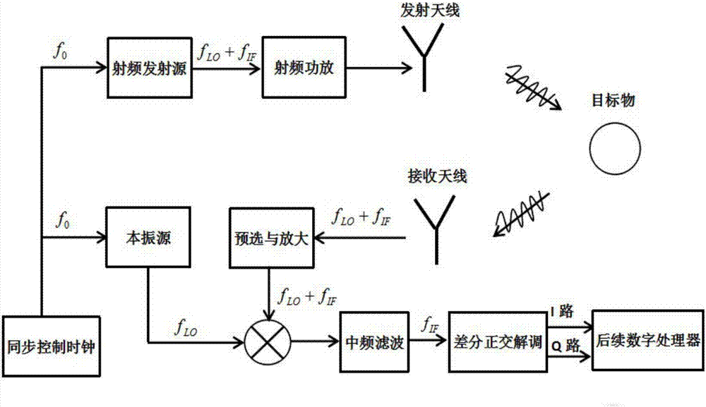
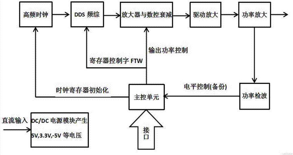
[0021] Such as figure 1 Shown is the functional block diagram of the entire step frequency radar system. It can be seen from the figure that the radio frequency transmission source and the local oscillator are important components of the entire hardware system. The radio frequency transmission source contains a radio frequency gain adjustment module and a power amplifier part at the end. The purpose is to increase the output power of the step frequency signal at each frequency point to the index 20W required by the system. The local oscillator source controlled by the synchronous control clock is only responsible for generating a local oscillator signal that is coherent with the radio frequency transmitting source, and amplifies the local oscillator signal to a specified value +17dBm (this is mainly because the selected mixer some functions). There are also the transmitting antenna and the receiving antenna, which are used to transmit the stepping radio frequency signal and r...


PUM


Abstract

The invention discloses a borehole radar step frequency controllable-mode signal source and belongs to a hardware component unit of a borehole radar logging system. The signal source comprises a radio frequency emission source and a local oscillator source, which are used for generating an emission signal and a local oscillator signal separately, wherein the radio frequency emission source and the local oscillator source are used for ensuring the coherence of the radio frequency signal and the local oscillator signal through a synchronous control clock. For the signal source in a directional borehole radar system of a step frequency system for depth logging, the controllable-mode signal source has the advantages of controllable mode, ns-scale fast frequency switching, a controllable step value, high output signal power and a wide frequency range.

Description

technical field [0001] The invention belongs to the hardware component unit of the radar logging system in the well. It is mainly used to generate wide-band, high-power step-frequency radar signals. The output step value and output frequency range can be programmed, and the output mode can be FM continuous wave, step Controllable adjustment between continuous wave and pulse-to-pulse step frequency wave. One way generates radio frequency signals, and the other way generates local oscillator signals, which together form a signal source. Background technique [0002] With the increasing demand of human beings for underground resources such as oil and gas, people's research on underground detection technology is increasing day by day. This requires in-depth research on resource distribution and geological structure, and the high cost of experiments urgently requires a high-precision, high-efficiency logging method. The borehole radar logging system is the product of applying b...

Claims


Application Information

Patent Timeline
IPC IPC(8): G05F1/66
CPCG05F1/66
Inventor 赵青厉华洋马春光谢龙昊霍健健
Owner UNIV OF ELECTRONIC SCI & TECH OF CHINA
Learn More