
Paper pulp stirring device

A stirring device and pulp technology, applied in mixers with rotating stirring devices, mixer accessories, transportation and packaging, etc., can solve the problems of inconvenient internal cleaning, low stirring efficiency, inconvenient discharge, etc., to achieve convenient cleaning, High stirring efficiency and the effect of preventing internal deposition

Inactive Publication Date: 2017-09-15
合肥励仙电力工程有限公司
View PDF2 Cites 6 Cited by
  • Summary
  • Abstract
  • Description
  • Claims
  • Application Information

AI Technical Summary

Problems solved by technology

Pulp needs to be mechanically processed during the preparation process, and a pulp stirring device is required to stir it evenly. However, most of the pulp stirring devices currently on the market have a single structure, low stirring efficiency, and inconvenient internal cleaning.
[0003] The announcement number is CN205672862U, and the announcement date is November 9, 2016. The Chinese utility model discloses a pulp stirring device, which involves the technical field of papermaking, including a kettle body, a pulp stirring paddle, a motor, a pulp stirring paddle support and an ultrasonic device. The lower part of the kettle body is provided with a partition, and the pulp stirring paddle is located in the middle of the kettle body above the partition. The pulp stirring paddle includes a stirring shaft and a stirring blade, and the stirring blade is arranged on the stirring shaft. The top is connected with the motor installed on the top of the kettle body, the stirring shaft is also equipped with a pulp stirring paddle bracket that can adjust the height freely, and the kettle body below the partition is equipped with an ultrasonic device, which includes an ultrasonic vibration plate, an acoustic sensor and a power interface , the ultrasonic vibration plate and the power interface are connected in series through the acoustic sensor, and the pulp is ultrasonically treated by the ultrasonic device, which effectively prevents the pulp from depositing inside the kettle body, and achieves the uniform mixing of the pulp inside the kettle body for stirring treatment, although the stirring device solves the problem of The problem of internal deposition is eliminated, but there are still problems such as low stirring efficiency and inconvenient discharge.

Method used


Image

  • Paper pulp stirring device
  • Paper pulp stirring device

Examples


Embodiment Construction

[0032] Below in conjunction with specific embodiment, further illustrate the present invention. These examples are only for illustrating the present invention and are not intended to limit the scope of the present invention. In the description of the present invention, it should be noted that unless otherwise specified and limited, the terms "installation", "installation" and "connection" should be interpreted in a broad sense, for example, it can be a fixed connection or an optional connection. Detachable connection, or integral connection; it can be mechanical connection or electrical connection; it can be direct connection or indirect connection through an intermediary, and it can be the internal communication of two components. Those of ordinary skill in the art can understand the specific meanings of the above terms in the present invention in specific situations.

[0033] Now in conjunction with the accompanying drawings, the structural features of the present invention...


PUM


Abstract

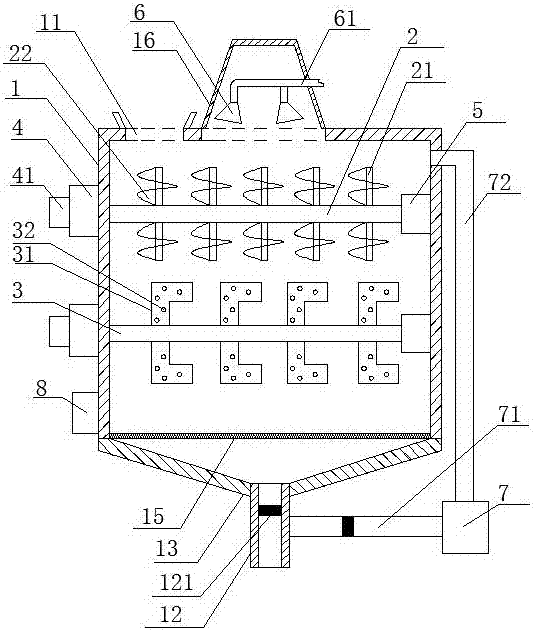
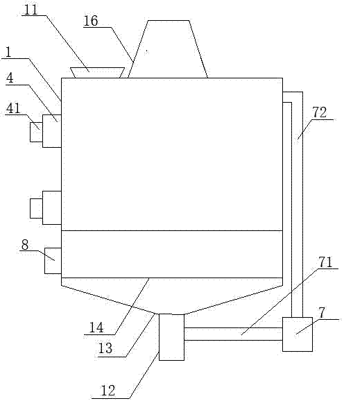
The invention discloses a paper pulp stirring device, and belongs to the technical field of paper pulp preparation. The paper pulp stirring device comprises a stirring barrel; the stirring barrel comprises a feed inlet arranged on the top, a discharge pipe arranged on the bottom, and a stirring mechanism arranged in an internal cavity; the center of the top surface of the stirring barrel stretches to form a cavity upwards; the cavity is communicated with the internal cavity of the stirring barrel; a spray mechanism is arranged in the cavity, and is used for downward washing of the internal cavity of the stirring barrel. The paper pulp stirring device can be used for stirring and dispersing paper pulp effectively, no deposition is generated in the internal part, stirring efficiency is high, washing is convenient, operation is simple, and application is convenient.

Description

technical field [0001] The invention belongs to the technical field of pulp preparation, and in particular relates to a pulp stirring device. Background technique [0002] Pulp is a fibrous substance made from plant fibers through different processing methods. According to the processing method, it can be divided into mechanical pulp, chemical pulp and chemical mechanical pulp; it can also be divided into wood pulp, straw pulp, hemp pulp, reed pulp, sugarcane pulp, bamboo pulp, rag pulp, etc. according to the fiber raw materials used. According to different purity, it can be divided into refined pulp, bleached pulp, unbleached pulp, high-yield pulp, semi-chemical pulp, etc. Pulp needs to be mechanically processed during the preparation process, and a pulp stirring device is required to uniformly stir it. However, most of the pulp stirring devices currently on the market have a relatively simple structure, low stirring efficiency, and inconvenient internal cleaning. [0003...

Claims


Application Information

Patent Timeline
IPC IPC(8): B01F5/10B01F7/04B01F15/00
CPCB01F25/52B01F27/701B01F27/2322B01F27/191B01F35/1453B01F35/187B01F2101/47
Inventor 伍文慧
Owner 合肥励仙电力工程有限公司
Learn More