
Bionic mechanical arm
A bionic machine and arm technology, applied in the field of bionic prosthetics, can solve the problems of difficult maintenance, high cost, complex structure, etc., and achieve the effects of high space utilization, low cost and small size
Patent Information
- Authority / Receiving Office
- CN · China
- Patent Type
- Applications(China)
- Current Assignee / Owner
- Publication Date
- 2017-09-15
- Estimated Expiration
- Not applicable · inactive patent
Smart Images
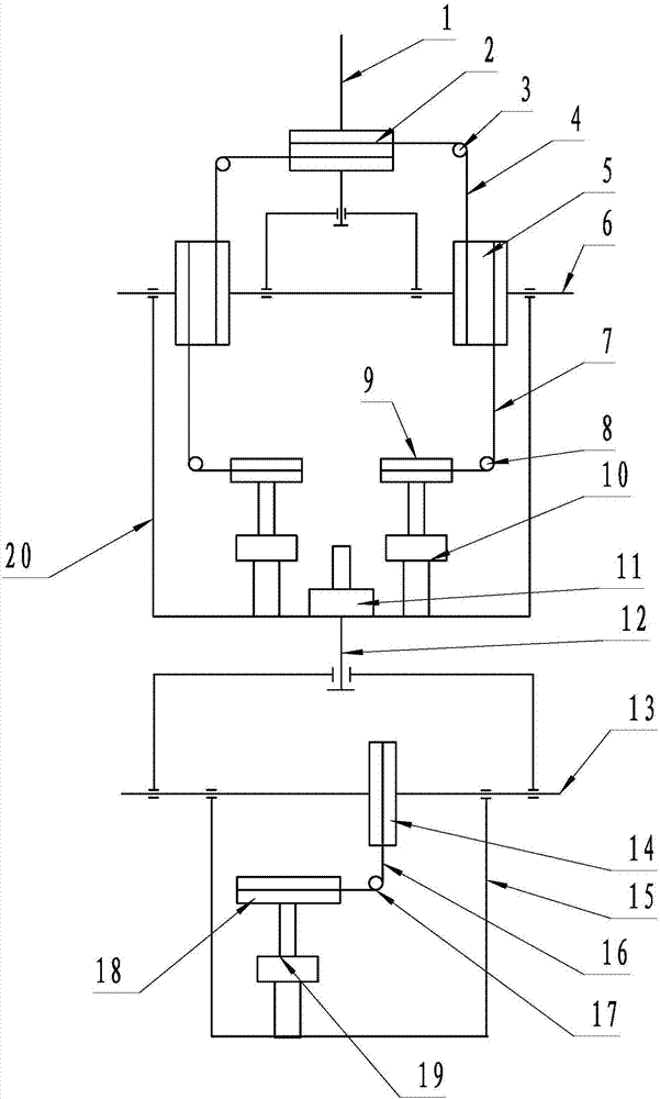
Figure 1
Abstract
Description
technical field
[0001] The patent of the invention relates to the technical field of bionic prosthesis, and belongs to a bionic mechanical arm. Background technique
[0002] Prosthetic limbs are artificial limbs manufactured and assembled to restore the shape and function of the human body and to compensate for the defects caused by amputation. Installing prosthetic limbs is an important means for amputees to recover and return to society. The structural design of the bionic robotic arm is a key component in the design of prosthetics. The volume, weight, appearance, and freedom of movement of the bionic robotic arm are all determined by the structural design of the robotic arm. The bionic manipulator requires small size, light weight, beautiful appearance, and can complete as many actions as possible that people first want to achieve. However, if it is required to be small in size and light in weight, its motion function will be limited. If the movement function is requir...
Examples
Embodiment Construction
[0020] see figure 1 Shown: a bionic mechanical arm, which includes a first shoulder joint axis 1, a second shoulder joint axis 6, a first elbow joint axis 12, and a second elbow joint axis 13, which are connected at the bottom of the first shoulder joint axis 1 There is a first shoulder joint shaft nylon roller 2 that rotates horizontally, and a first guide wheel 3 that moves downward is provided on both sides of the first shoulder joint shaft nylon roller 2, and a second shoulder joint shaft is provided at the bottom of the first guide wheel 3 6. The second shoulder joint shaft 6 is provided with two vertical second shoulder joint shaft nylon rollers 5, between the first shoulder joint shaft nylon roller 2, the first guide wheel 3 and the second shoulder joint shaft nylon roller 5 The first shoulder joint shaft steel wire 4 is connected between them;
[0021] The first motor 21 and the second motor 10 of vertical rotation are arranged side by side at the bottom of the second...