Laminated slab type concrete shear wall steel bar snap-fit connecting joint and construction method

A concrete shear wall and snap connection technology, applied in the direction of walls, structural elements, building components, etc., can solve problems such as poor effect, and achieve the effects of reliable connection, tight connection and convenient construction

Pending Publication Date: 2017-09-15
姜雯雯
View PDF6 Cites 1 Cited by
  • Summary
  • Abstract
  • Description
  • Claims
  • Application Information

AI Technical Summary

Problems solved by technology

Hollow walls have obvious advantages, but at this stage, the connection form of laminated slab concrete shear walls usually uses steel bars to anchor in the cast-in-situ concrete inside the cavity of the wall. Poor force effect

Method used


Image

  • Laminated slab type concrete shear wall steel bar snap-fit connecting joint and construction method
  • Laminated slab type concrete shear wall steel bar snap-fit connecting joint and construction method
  • Laminated slab type concrete shear wall steel bar snap-fit connecting joint and construction method

Examples


Embodiment 1

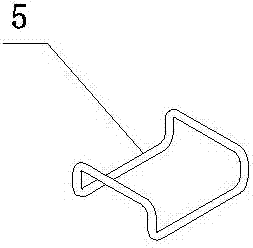
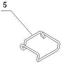
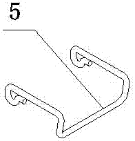
[0033] A kind of fastening connection node of reinforced slab concrete shear wall, which consists of: laminated slab concrete shear wall 1, fastening steel bar 5 and spring bar 6, and the described laminated slab concrete shear wall consists of two layers Concrete thin slabs, and the two thin slabs are formed as a whole by lattice steel bars 2, and the laminated slab concrete shear wall includes longitudinal steel bars 3 and transverse steel bars 4, and the short sides of the transverse steel bars are built with the According to different forms, the fastening steel bar is arranged on the short side of the transverse steel bar in advance and the spring bar is added according to the specific form of the fastening steel bar, so that the spring bar has a reaction force, After the installation of the spring bars is completed, they are fixed with the transverse steel bars by welding.

Embodiment 2

[0035] According to the fastening connection node of the reinforced slab concrete shear wall described in Example 1, the in-situ concrete 7 is cast in the cavity of the mouth of the laminated slab concrete shear wall, and the surface of the thin concrete slab is provided with Operation hole 8.

Embodiment 3

[0037] According to the buckled connection node of the reinforced slab concrete shear wall described in embodiment 1 or 2, the described transverse steel bar is in the form of a ring, and the buckled steel bar is formed into a three-dimensional U-shaped structure and a three-dimensional S-shaped structure by bending. structure, three-dimensional P-type structure and three-dimensional Z-type structure.


PUM


Abstract

The invention discloses a laminated slab type concrete shear wall steel bar snap-fit connecting joint and a construction method. The connecting mode commonly adopts that steel bars are anchored into cast-in-situ concrete in a wall cavity, structural steel bars are forced to be disconnected, force cannot be directly transmitted, structural safety stock is lowered, the overall stiffness of a wall body is weakened, and the anti-shearing capacity of the wall body is lowered. The laminated slab type concrete shear wall steel bar snap-fit connecting joint comprises a laminated slab type concrete shear wall (1), snap-fit steel bars (5) and spring bars (6). The laminated slab type concrete shear wall is composed of two layers of concrete thin plates which form a whole through lattice steel bars (2), and the laminated slab type concrete shear wall comprises longitudinal steel bars (3) and transverse steel bars (4); and the snap-fit steel bars are set up at the short edges of the transverse steel bars, are arranged at the short edges of the transverse steel bars in advance according to the different modes and additionally provided with the spring bars according to the specific modes of the snap-fit steel bars.

Description

Technical field: [0001] The invention relates to a fastening connection node of a composite slab concrete shear wall and a construction method thereof. Background technique: [0002] At present, my country's assembly of integral reinforced concrete structures is dominated by solid walls. With the development of the industry, through the practice of a large number of projects, the advantages of hollow walls have gradually been tapped. The requirements are low, and the tower crane used in the traditional cast-in-place concrete structure can also meet the requirements; the amount of component formwork is small and the formwork material is cheap, and the amortized amount is small; the component thickness is small, the steam curing time is short, and the component strength increases quickly; compared with solid walls As far as it is concerned, the post-casting tape formwork is canceled in the true sense. Hollow walls have obvious advantages, but at this stage, the connection form ...

Claims


Application Information

Patent Timeline
Patent Type & Authority Applications(China)
IPC IPC(8): E04B2/86E04C5/16
CPCE04B2/86E04B2/8652E04C5/162
Inventor 姜雯雯闫佳莹
Owner 姜雯雯
Why Eureka
Try Eureka