Drill-rod fixed clamp and control method thereof

A technology of drill pipe and dead sticking, which is applied in the direction of earthwork drilling, wellbore/well components, sealing/isolation, etc., which can solve problems such as troublesome installation and disassembly, operation failure, and heavy weight, so as to increase safety and stability performance, increased stability and safety, easy and convenient installation and use

Active Publication Date: 2017-09-15
CHENGDU ZHUOXIN IND
View PDF11 Cites 1 Cited by
  • Summary
  • Abstract
  • Description
  • Claims
  • Application Information

AI Technical Summary

Problems solved by technology

[0003]1. The control system is complex, the operating system has 4 operating handles, and the operation steps are cumbersome;
[0004]2. The reversing valve is used to close the hydraulic cylinder under pressure. Since the reversing valve cannot be effectively sealed, there is pressure leakage in the hydraulic cylinder, which eventually causes operation failure;
[0005]3. The system returns oil to the hydraulic power station. Due to the opening pressure of the oil return check valve of the hydraulic station, the unloading of the hydraulic pressure is not complete, causing the piston spring to fail to push back the piston so that the drill Pole dead card cannot be unlocked
Due to the heavy weight of the hydraulic locking device and dead card components, more manpower and spreaders are required for installation and disassembly, which brings inevitable troubles to installation and disassembly

Method used


Image

  • Drill-rod fixed clamp and control method thereof
  • Drill-rod fixed clamp and control method thereof
  • Drill-rod fixed clamp and control method thereof

Examples


Embodiment 1

[0069] As a preferred embodiment of the present invention, with reference to the attached figure 1 To attach Figure 7 , this embodiment discloses a drill pipe stuck and its control method, this embodiment includes:

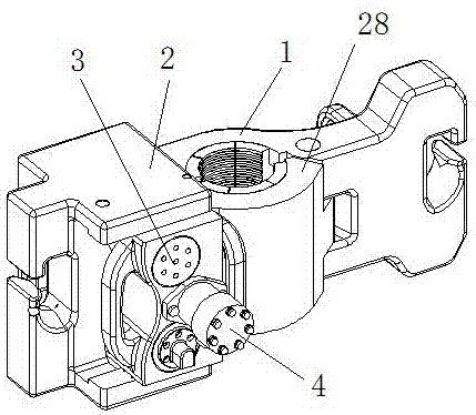
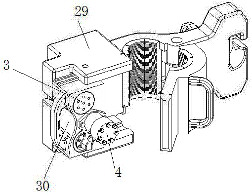
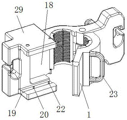
[0070] A drill pipe deadlock, including deadlock assembly I1 and deadlock assembly II28, one end of deadlock assembly I1 and deadlock assembly II28 is hinged together; one end of deadlock assembly I1 is fixedly connected to locking device 2, and the other end is connected to deadlock The assembly II28 is hinged; one end of the deadlock assembly II28 is hinged with the deadlock assembly I1, and the other end is a movable end; the locking device 2 includes a locking device body 29 and a sliding part 30 that can slide along the locking device body 29, A groove 18 is provided between the sliding part 30 and the locking device body 29 for placing the movable end of the dead card assembly II 28 .

[0071] The locking device body 29 is provided with a C-shaped groove ...

Embodiment 2

[0115] As a preferred embodiment of the present invention, with reference to the attached figure 1 to attach Figure 7 , this embodiment discloses a drill pipe deadlock, this embodiment includes:

[0116] A drill pipe deadlock, including deadlock assembly I1 and deadlock assembly II28, one end of deadlock assembly I1 and deadlock assembly II28 is hinged together; one end of deadlock assembly I1 is fixedly connected to locking device 2, and the other end is connected to deadlock The assembly II28 is hinged; one end of the deadlock assembly II28 is hinged with the deadlock assembly I1, and the other end is a movable end; the locking device 2 includes a locking device body 29 and a sliding part 30 that can slide along the locking device body 29, A groove 18 is provided between the sliding part 30 and the locking device body 29 for placing the movable end of the dead card assembly II 28 .

Embodiment 3

[0118] As a preferred embodiment of the present invention, with reference to the attached figure 1 to attach Figure 7 , this embodiment discloses a drill pipe deadlock, this embodiment is basically the same as Embodiment 2, the difference is:

[0119] The locking device body 29 is provided with a C-shaped groove corresponding to the size of the sliding part 30, and the sliding part 30 is arranged in the C-shaped groove; the side walls of the upper and lower ends of the C-shaped groove are provided with slide grooves 19 , a slider 25 corresponding to the sliding groove 19 is provided at a position corresponding to the sliding part 30 , and the slider 25 is arranged in the sliding groove 19 .


PUM


Abstract

The invention relates to a drill-rod fixed clamp device for preventing blowout of oil and gas field well drilling, in particular to a drill-rod fixed clamp and a control method thereof. The drill-rod fixed clamp comprises a first fixed clamp assembly and a second fixed clamp assembly, and the first fixed clamp assembly is hinged to one end of the second fixed clamp assembly; one end of the first fixed clamp assembly is fixedly connected with a locking device, and the other end of the first fixed clamp assembly is hinged to the second fixed clamp assembly; one end of the second fixed clamp assembly is hinged to the first fixed clamp assembly, and the other end of the second fixed clamp assembly is a free end; and the locking device comprises a locking device body and a sliding part capable of sliding along the locking device body, and a groove used for placing the free end of the second fixed clamp assembly is formed between the sliding part and the locking device body. According to the drill-rod fixed clamp and the control method thereof, the first fixed clamp assembly and the locking device are fixedly connected, the locking device is arranged to be of a push-pull structure, and locking and unlocking of the second fixed clamp assembly are completed by pushing and pulling the sliding part, so that the fixed clamp assemblies and the locking device are integrated; and one-time hoisting is only needed to complete installation and removal, and installation and removal are both very convenient.

Description

technical field [0001] The invention relates to a device for dead sticking of a drill pipe for blowout prevention in oil and gas field drilling, in particular to a dead stick of a drill pipe and a control method thereof. Background technique [0002] In the field of development and exploration of oil and gas fields, when drilling operators obtain oil and gas reservoirs with various pressures, the bottom hole pressure exerts a great force on the drilling fluid and drilling tools to push outward. A kick, or blowout, occurs when the bottom hole pressure is greater than the counterweight force exerted by the driller. At this time, there is a special blowout preventer at the wellhead to prevent the liquid in the well from spraying outward from the surface of the drilling tool, and the drilling tool generally has an internal blowout preventer to prevent the liquid in the well from escaping upward from the water hole of the drilling tool. But at this time, the pressure in the well...

Claims


Application Information

Patent Timeline
Patent Type & Authority Applications(China)
IPC IPC(8): E21B33/06
CPCE21B33/06
Inventor 陈伦俊池振华卢伟
Owner CHENGDU ZHUOXIN IND
Why Eureka
Try Eureka