
Layout method for optical fiber grating monitoring system for mine gas extraction

A fiber grating and gas drainage technology, which is applied in the direction of gas discharge, mining equipment, safety devices, etc., can solve problems such as poor ventilation, poor gas pollution, and poor underground environment, so as to improve resource utilization, The effect of high measurement accuracy and long signal transmission distance

Inactive Publication Date: 2017-09-15
CHINA UNIV OF MINING & TECH
View PDF6 Cites 1 Cited by
  • Summary
  • Abstract
  • Description
  • Claims
  • Application Information

AI Technical Summary

Problems solved by technology

Most of the measurements are made artificially, and the underground environment is harsh and the ventilation environment is poor, so there are many potential safety hazards
Most of the abandoned mines are not properly treated, and a large amount of gas spills out to pollute the environment

Method used


Image

  • Layout method for optical fiber grating monitoring system for mine gas extraction
  • Layout method for optical fiber grating monitoring system for mine gas extraction
  • Layout method for optical fiber grating monitoring system for mine gas extraction

Examples


Embodiment 1

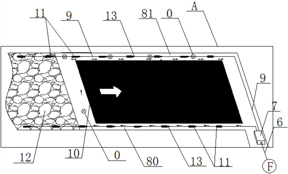
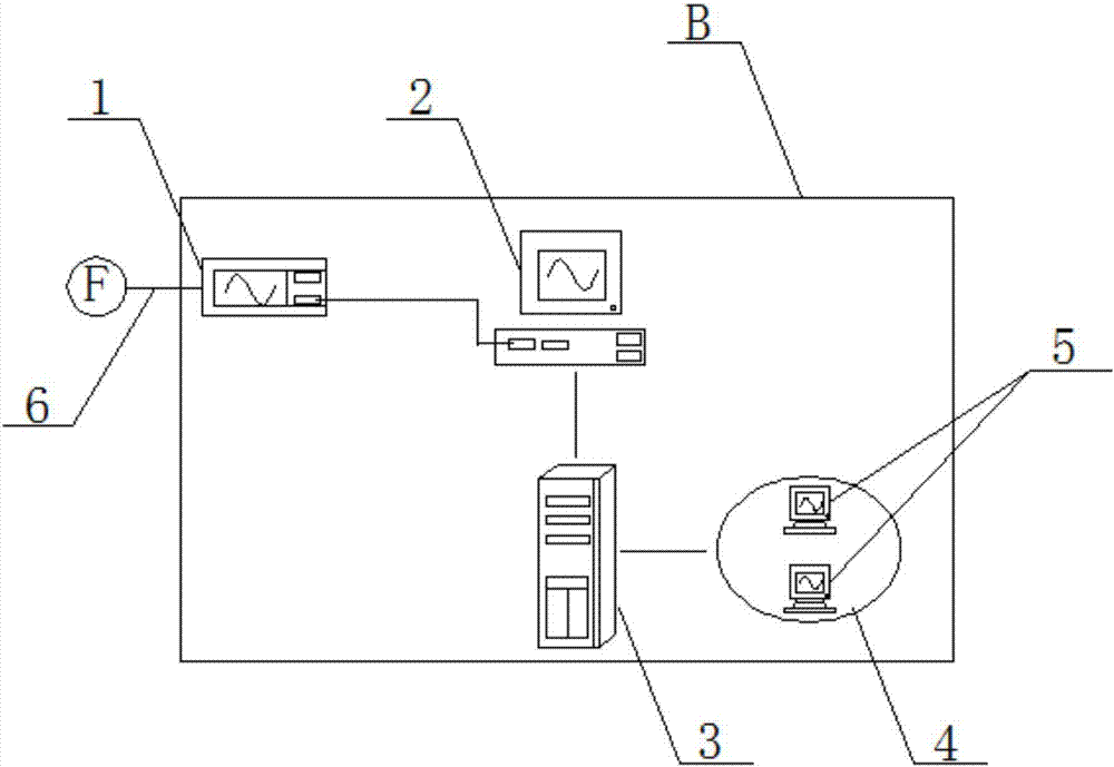
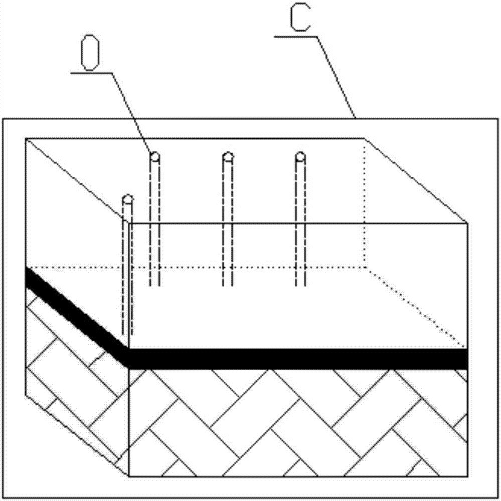
[0058] Embodiment 1: A fiber grating monitoring system layout method for gas drainage in high-gas mines. Fiber grating gas concentration sensors 11 are simultaneously deployed during the excavation of the transport lane 80 and the return air lane 81, and are installed on the top of the lane. The fiber grating gas concentration sensors 11 are arranged horizontally at intervals of 10-15m. Each fiber grating gas concentration sensor 11 is connected in series through the communication optical fiber 9, and the communication optical fiber 9 is connected with the mining transmission optical cable 6 through the optical fiber terminal box 7; the mining optical cable 6 is connected with the input end of the fiber grating static demodulator 1, and The output terminal of the controller 1 is connected to the monitoring computer 2, and the monitoring computer 2 performs data sharing with the client 5 through the network server 3 and the mine local area network 4; a gas drainage drilling grou...


PUM


Abstract

The invention discloses a layout method for an optical fiber grating monitoring system for mine gas extraction and belongs to layout methods for the optical fiber grating monitoring system. The layout method comprises the steps that (1) as for an underground optical fiber grating gas concentrationsensor layout system, optical fiber grating gas concentrationsensors are arranged on the tops of a transportation roadway and an air return roadway, spaced by 10-15 m horizontally, connected in series through a communication optical fiber, and connected with a mining transmission optical cable through an optical fiber terminal box; (2) as for a ground monitoring station layout system, the mining transmission optical cable is connected with the input end of an optical fiber grating interrogator, and the interrogator is connected with a monitor computer; and (3) as for a gas extraction drilling assembly layout system, a gas extraction drilling assembly is disposed 5 meters behind the initial mining working face and 30 m away from the transportation roadway, and other gas extraction drilling assemblies are horizontally disposed in the air return roadway every 200 m. The layout method has the advantages that roadway gas is continuously detected and monitored online, installation is easy, gas is prevented from accumulating at the upper corner, the utilization rate of resources is improved, and high yield and high efficiency are achieved.

Description

technical field [0001] The invention relates to a method for arranging an optical fiber grating monitoring system, in particular to an arranging method for an optical fiber grating monitoring system used for mine gas drainage. [0002] The present invention is an arrangement method of an optical fiber grating monitoring system, specifically an arrangement method based on the application of optical fiber grating monitoring in high-gas mine mining and gas drainage in the later stage, and is applied to high-gas mine mining and goaf gas monitoring in the later stage Drainage is also suitable for the utilization of abandoned mine gas. Background technique [0003] China's coal resources are about 5×10 12 t, the symbiotic and associated coalbed methane resources are also very large, ranking third in the world, second only to Russia and Canada, and about three times the reserves of the United States. The national coalbed methane resources buried within 2000m are 30×10 12 ~35×10 ...

Claims


Application Information

Patent Timeline
IPC IPC(8): E21F17/18E21F7/00
CPCE21F7/00E21F17/18
Inventor 方新秋冯裕堂梁敏富吴刚蔡成锋卢海洋
Owner CHINA UNIV OF MINING & TECH
Learn More