New Smart Home Lighting Devices

A technology for smart home and lighting devices, applied in lighting devices, lighting auxiliary devices, fixed lighting devices, etc., can solve problems such as potential safety hazards of LED equipment, impact on the operating life of lighting equipment, light pollution, etc., and achieve a high degree of integration and operation automation. , Good data communication ability, flexible and convenient use

Active Publication Date: 2019-07-05
无锡韦森仕安科技有限公司
View PDF5 Cites 0 Cited by
  • Summary
  • Abstract
  • Description
  • Claims
  • Application Information

AI Technical Summary

Problems solved by technology

[0002] At present, compared with traditional lighting equipment, LED lighting equipment has the characteristics of high brightness, low energy consumption and long operating life, so it has been widely used. Among them, LED lighting equipment in smart home and smart home systems has also become this type of intelligent system. However, when controlling lighting equipment in the current smart home system, the traditional control method is often adopted, that is, only the on-off working state of the lighting equipment can be controlled, but the operating state of the lighting equipment can be controlled. The lighting intensity and other parameters lack effective adjustment capabilities, and at the same time lack the ability to adjust the lighting angle when the lighting equipment is running, resulting in relatively high energy consumption during the operation of the current lighting equipment, and it is easy to cause light pollution. At the same time, in the lighting process , and it is impossible to accurately control the efficiency of waste heat dissipation work when LED lighting equipment is running, so it also causes a greater safety hazard when LED equipment is running, and has a greater impact on the operating life of LED lighting equipment. Therefore, for this phenomenon , there is an urgent need to develop a new type of lighting equipment for smart home systems to meet the needs of actual use

Method used


Image

  • New Smart Home Lighting Devices
  • New Smart Home Lighting Devices

Examples


Embodiment Construction

[0015] In order to make the technical means, creative features, goals and effects achieved by the present invention easy to understand, the present invention will be further described below in conjunction with specific embodiments.

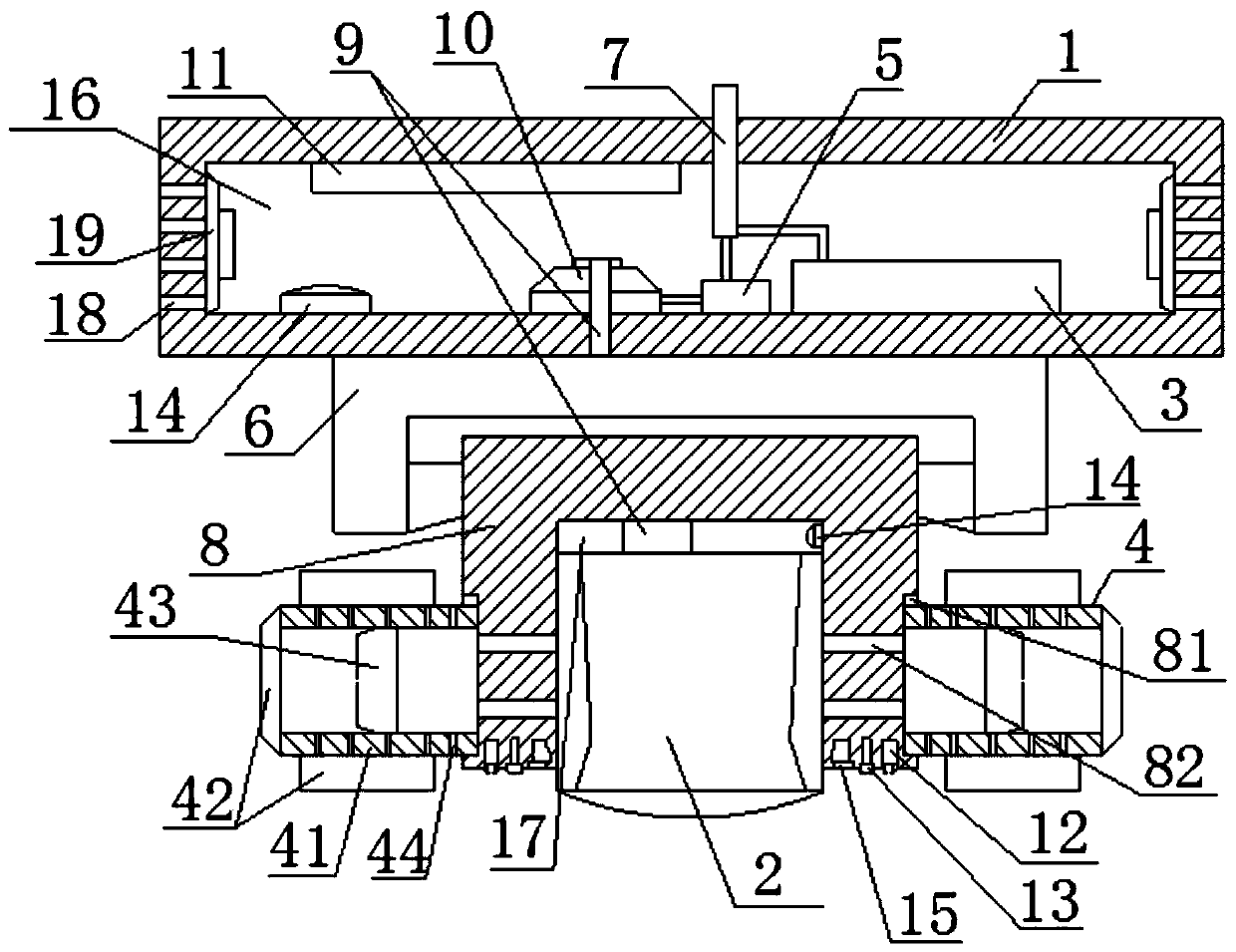
[0016] Such as figure 1 The new smart home lighting device includes a bearing base 1, an LED lighting lamp holder 2, an auxiliary driving power supply 3, a cooling block 4, a thyristor switch 5, a turntable mechanism 6, a main terminal 7, a bearing block 8, Connecting electrode 9, voltage regulation and rectification circuit 10, control circuit 11 based on wireless data communication unit, ultrasonic distance measuring device 12, human body proximity sensor 13, temperature sensor 14, light sensor 15, wherein the cross section of the bearing base 1 is a rectangular structure The load compartment 16 of the load compartment 16, the auxiliary drive power supply 3, the thyristor switch 5, the voltage regulation rectifier circuit 6, and the control circ...


PUM


Abstract

The invention relates to a novel illuminating device for smart home. The device comprises a bearing base, an LED illuminating lamp cap, an auxiliary driving power supply, cooling blocks, a silicon-controlled switch, a main wiring column, a bearing block, connecting electrodes, a voltage regulating and rectifying circuit, a control circuit based on a wireless data communication unit, ultrasonic distance measuring devices, human body proximity sensors, temperature sensors, and illumination sensors, wherein a bearing cabin with the cross section as a rectangular structure is arranged in the bearing base; the auxiliary driving power supply, the silicon-controlled switch, the voltage regulating and rectifying circuit and the control circuit based on the wireless data communication unit are all embedded in the bearing cabin; the back end surface of the bearing block is hinged to the front end surface of the bearing base through a turntable mechanism; at least one positioning groove is formed in the front end surface of the bearing block; and the LED illuminating lamp cap is embedded in the positioning groove. The device is high in integration and operation automation, and effectively reduces the energy consumption of the illumination operation and overcomes the light pollution phenomenon easily generated in traditional illuminating equipment when improving flexibility, accuracy and convenience of the illumination operation.

Description

technical field [0001] The invention relates to an intelligent lighting device, specifically a new type of intelligent lighting device for household use. Background technique [0002] At present, compared with traditional lighting equipment, LED lighting equipment has the characteristics of high brightness, low energy consumption and long operating life, so it has been widely used. Among them, LED lighting equipment in smart home and smart home systems has also become this type of intelligent system. However, when controlling lighting equipment in the current smart home system, the traditional control method is often adopted, that is, only the on-off working state of the lighting equipment can be controlled, but the operating state of the lighting equipment can be controlled. The lighting intensity and other parameters lack effective adjustment capabilities, and at the same time lack the ability to adjust the lighting angle when the lighting equipment is running, resulting i...

Claims


Application Information

Patent Timeline
Patent Type & Authority Patents(China)
IPC IPC(8): F21S8/04F21V21/15F21V23/00F21V23/04F21V29/74F21V29/67F21V29/83F21Y115/10
CPCF21S8/04F21V21/15F21V23/003F21V23/0464F21V23/0471F21V29/67F21V29/74F21V29/83F21Y2115/10
Inventor 王为新李四海
Owner 无锡韦森仕安科技有限公司
Why Eureka
Try Eureka