Using method of garbage incineration device

A technology of waste incineration and incineration chamber, which is applied in the field of environmental protection and sanitation to achieve the effects of reducing generation and emission, increasing temperature and high calorific value

Inactive Publication Date: 2017-09-15
CHENGDU SINOMETALLURGY ENERGY CONSERVATION ENVIRONMENTAL PROTECTION ENG CO LTD
View PDF3 Cites 0 Cited by
  • Summary
  • Abstract
  • Description
  • Claims
  • Application Information

AI Technical Summary

Problems solved by technology

[0006] The invention provides a method for using a garbage incineration device to solve the problem that the existing technology is not suitable for the actual garbage situation in our country and produces a kind of highly toxic substance dioxin that is difficult to handle due to the substandard temperature

Method used


Image

  • Using method of garbage incineration device
  • Using method of garbage incineration device

Examples


Embodiment 1

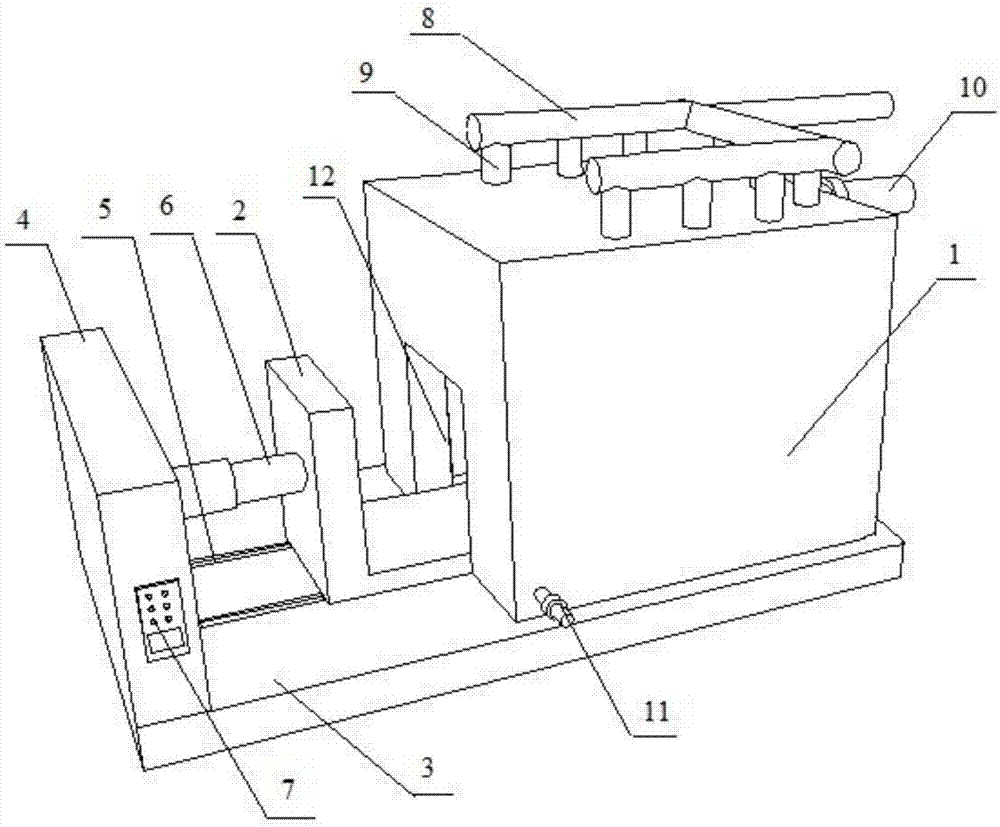
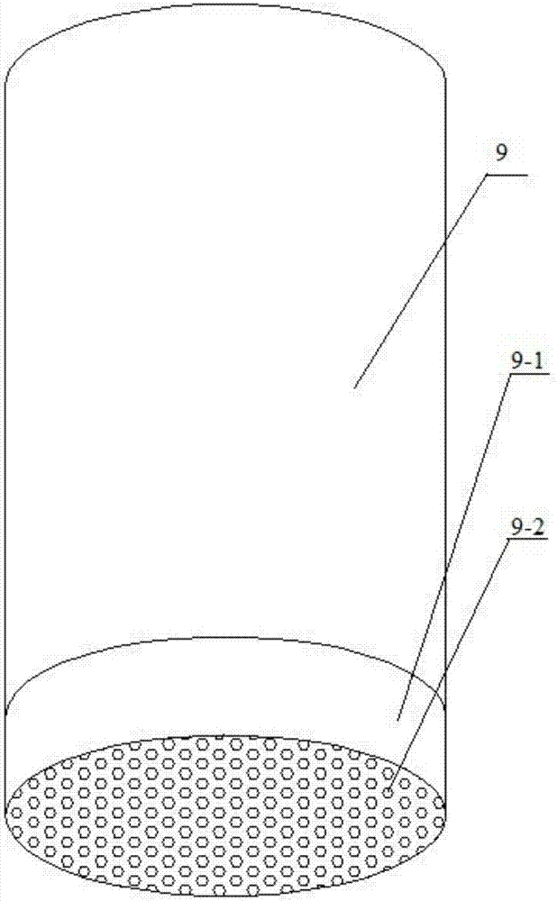
[0024] like figure 1 As shown, it is a kind of garbage incineration device, which includes an incineration chamber 1 arranged on the foundation 3. The incineration chamber 1 is provided with a feed port 12 communicating with the inside of the incineration chamber 1, an oxygen pipe 11 and an air outlet pipe 10. The inside of the chamber 1 is provided with an ignition device, and the outside of the incineration chamber 1 is provided with a control panel 7 for controlling the ignition device and detecting the internal temperature of the incineration chamber 1, and the feed port 12 is provided with a feed door 2 covering the feed port 12, It also includes a pressure pump and an oil storage tank. The top of the incineration chamber 1 is provided with a recovery oil injection pipeline 8 connecting the pressure pump and the oil storage tank. On the recovery oil injection pipeline 8, a number of branch pipes extending to the interior of the incineration chamber 1 are evenly distributed...

Embodiment 2

[0035] Further optimization is carried out on the basis of the waste incineration device described in Embodiment 1. The slide rail 5 leading to the feed inlet 12 is provided on the foundation 3, and the slide rail 5 corresponding to the slide rail 5 is provided below the feed gate 2. Corresponding to the slider, the outer end of the slide rail 5 is provided with a vertical fixed wall 4 parallel to the feed door 2, and an edge for driving the feed door 2 is provided between the fixed wall 4 and the feed door 2. The slide rail 5 slides the inert cylinder 6; in order to ensure the heat preservation effect, the thickness of the feed door 2 is consistent with that of the incineration chamber 1, and its weight often weighs several hundred kilograms, which is difficult to manually move, and the temperature of the feed door 2 is relatively high after incineration. People will be in danger of being scalded when they get close to the feed door 2. The purpose of this embodiment is to solv...

Embodiment 3

[0037] On the basis of the waste incineration device described in Embodiment 2, further optimization is carried out. The control panel 7 is arranged on the fixed wall 4. The setting of this embodiment can keep the control panel 7 away from the high temperature incineration chamber 1 to avoid high temperature. Affect the service life of the control panel 7.


PUM


Abstract

The invention discloses a method for using a garbage incineration device, which comprises the following steps: ① closing the feeding door after feeding through the feeding port; The ignition device inside the chamber is incinerated until the temperature inside the incineration chamber reaches 1000°C on the control panel, close the control valve on the recovery oil injection pipeline, open the control valve on the gas outlet pipe, and discharge the incineration gas; ③ When the control panel displays incineration When the indoor temperature is lower than 850°C, close the control valve on the outlet pipe, open the control valve on the recovery oil injection pipeline, open the control valve on the outlet pipe when it reaches 850°C, and close the recovery oil injection pipeline when it reaches 1000°C ④ Repeat steps ③ until the incineration is complete, open the control valve on the outlet pipe, and turn out the waste incineration residue while keeping burning in the incineration chamber; ⑤ put in new waste after turning out the waste incineration residue, Repeat steps ①‑④.

Description

technical field [0001] The invention relates to the field of environmental sanitation treatment, in particular to a method for using a garbage incineration device. Background technique [0002] In the process of urbanization, garbage, as a product of urban metabolism, used to be a burden on urban development. Many cities in the world have been surrounded by garbage. At present, there are two ways to deal with garbage: landfill and incineration. Among them, the landfill takes up a lot of space, and the plastic products commonly used in modern life degrade slowly, which has a heavy burden on the environment. The heavy metal content in the leachate is large, and various bacteria and germs breed, which seriously pollutes the water quality in the landfill area. It can be seen that the landfill method is not a long-term development solution. [0003] The waste incineration treatment method is a process in which the waste is oxidized at a high temperature to reduce its volume thro...

Claims


Application Information

Patent Timeline
Patent Type & Authority Applications(China)
IPC IPC(8): F23G5/00F23G5/50
CPCF23G5/008F23G5/50F23G2209/102F23G2900/50007F23G2900/54402F23G2900/55
Inventor 王蓉
Owner CHENGDU SINOMETALLURGY ENERGY CONSERVATION ENVIRONMENTAL PROTECTION ENG CO LTD
Why Eureka
Try Eureka