Al technical title is built by PatSnap Al team. It summarizes the technical point description of the patent document.
A technology of ice pellets and ice making chambers, which is applied in the field of continuous ice pellet production equipment, can solve the problems of not being able to continuously produce round ice pellets, low ice pellet preparation efficiency, and easy melting of ice pellets, so as to ensure heat transfer Effect of driving temperature difference, light weight, and improving freezing speed
Inactive Publication Date: 2019-05-03
QINGDAO UNIV
View PDF6 Cites 0 Cited by
Summary
Abstract
Description
Claims
Application Information
AI Technical Summary
This helps you quickly interpret patents by identifying the three key elements:
Problems solved by technology
Method used
Benefits of technology
Problems solved by technology
[0003] There are three main ways to produce ice particles. One is the physical crushing method of large ice cubes. Generally, ice cubes of appropriate size are first frozen, then crushed, and then sieved to obtain ice particles with the required particle size. It cannot be continuously produced. Round ice particles are produced, and the ice particles are easy to melt during the crushing and screening process; the second is the vacuum rapid cooling method, which requires a complicated vacuum system, which is uneconomical, and the temperature for generating ice particles is high, and the practicability is poor; the third is refrigeration If the agent is in direct contact with the freezing method, the water droplets are easy to burst, and during the freezing process, the bonding phenomenon is serious
At present, although ice pellet production equipment is diverse and the technology is relatively mature, general ice production equipment requires large-scale crushing machinery, the system composition is complex, the volume is relatively large, the ice pellet preparation efficiency is low, and ice pellets need to be refrigerated
Method used
Image
Click on the blue label to locate the original text in one second.
Reading with bidirectional positioning of images and text.
Examples
Embodiment Construction
[0013] The technical solution of the present invention will be described in detail below in conjunction with the accompanying drawings, and the content of the present invention will be illustrated by means of the following examples, rather than limiting the scope of the present invention.
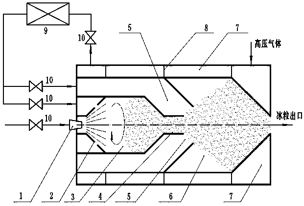
[0014] Such as figure 1 The continuous ice production device shown includes atomizing nozzle 1, swirl nozzle 2, ice making chamber 3, hollow pipe 4, hollow circulation nozzle 5, mixing chamber 6, pre-cooling chamber 7, swirl partition 8, Cryogenic refrigerator 9 and valve 10. The atomizing nozzle 1 and the swirl nozzle 2 are arranged at the front of the ice-making chamber 3, the atomizing nozzle 1 is arranged at the center, the swirl nozzle 2 is arranged around the atomizing nozzle 1, and a hollow pipe 4 is arranged at the end of the ice-making chamber 3, and the hollow pipe 4 The outside is a hollow circulation nozzle 5, the rear part of the hollow circulation nozzle 5 is a mixing chamber...
PUM
Abstract
The invention provides a continuous ice particle making device. The continuous ice particle making device comprises an atomizing nozzle, a swirl nozzle, an ice making compartment, a hollow pipe, a hollow circulation nozzle, a mixing chamber, a precooling chamber and the like. Water is atomized to generate water droplets through the atomizing nozzle, low-temperature swirl gas is sprayed through the swirl nozzle, the atomized water droplets are frozen to generate ice particles, and the low-temperature gas passes through the hollow circulation nozzle so as to continuously make ice particles. Under the action of swirl, injection, entrainment and mixing of the swirl nozzle and the hollow circulation nozzle, the ice particles are quickly generated, the particle size is uniform, and the intensity is high; the precooling chamber is precooled to be cool, and the cooling capacity is recycled, so that heat loss of the low-temperature gas is reduced and eliminated, and energy is saved. The system has the advantages of simple structure, small size, light weight and low manufacturing cost and can be used for continuously making the ice particles, and for example, the ice particles can be injected in application occasions such as surface cleaning, derusting, ice storage, food processing and the like.
Description
technical field [0001] The invention relates to an ice particle production device, in particular to a continuous ice particle production device. Background technique [0002] The preparation of ice particles with a certain temperature and particle size is in great demand in engineering. Finding a continuous and instant method of producing ice particles of a specific size, reducing the storage of ice particles and promoting the fluidization of ice particles is the key to accelerating the industrial application of ice particles. [0003] There are three main ways to produce ice particles. One is the physical crushing method of large ice cubes. Generally, ice cubes of appropriate size are first frozen, then crushed, and then sieved to obtain ice particles with the required particle size. It cannot be continuously produced. Round ice particles are produced, and the ice particles are easy to melt during the crushing and screening process; the second is the vacuum rapid cooling me...
Claims
Application Information
Patent Timeline
Application Date:The date an application was filed.
Publication Date:The date a patent or application was officially published.
First Publication Date:The earliest publication date of a patent with the same application number.
Issue Date:Publication date of the patent grant document.
PCT Entry Date:The Entry date of PCT National Phase.
Estimated Expiry Date:The statutory expiry date of a patent right according to the Patent Law, and it is the longest term of protection that the patent right can achieve without the termination of the patent right due to other reasons(Term extension factor has been taken into account ).
Invalid Date:Actual expiry date is based on effective date or publication date of legal transaction data of invalid patent.