Stirring, mixing and reduction device
A technology of stirring, mixing and dividing device, applied in measuring devices, analyzing materials, sampling, etc., can solve the problems of inconvenient feeding, dust leakage, environmental pollution, etc. Effect
- Summary
- Abstract
- Description
- Claims
- Application Information
AI Technical Summary
Problems solved by technology
Method used
Image

Examples
Embodiment
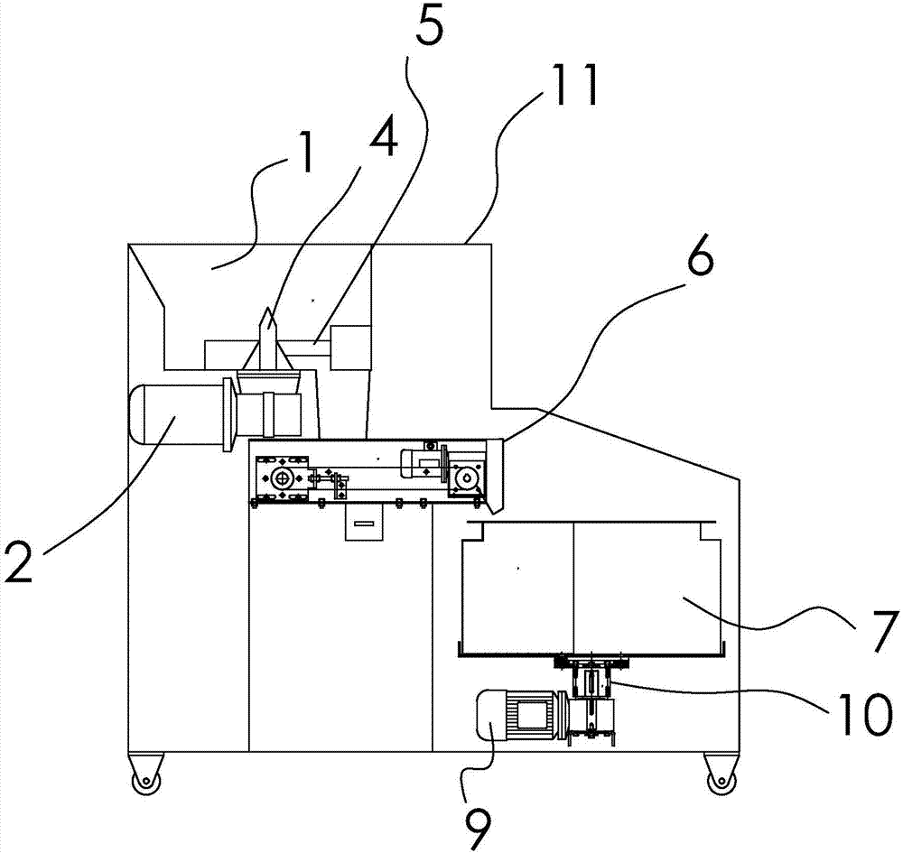
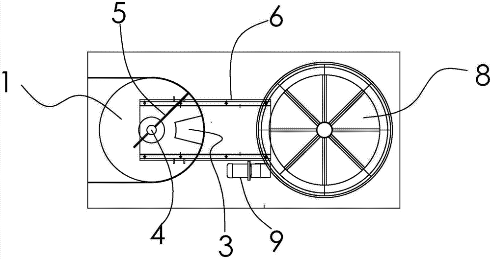
[0024] figure 1 and 2 Shown, a kind of stirring and mixing shrinkage device comprises:
[0025] A stirring mixer, the mixer is made up of a stirring and mixing straight barrel 1 and a first motor 2 located below the straight barrel 1; the bottom surface of the straight barrel 1 is provided with a discharge port 3, and the discharge port 3. It is arranged at one side of the center of the bottom surface of the straight barrel 1; the stirring and mixing straight barrel 1 is provided with an agitator, and the agitator is composed of a stirring shaft that passes through the center of the straight barrel 1 and is connected to the first motor 2. 4 and a stirring blade 5 arranged inside the straight barrel 1 and vertically connected to the stirring shaft 4.
[0026] Compared with the cone barrel, the straight barrel 1 can increase the volume; the first motor 2 is arranged under the straight barrel 1, and the overall installation and operation are more stable.
[0027] A small belt ...
PUM
 Abstract
Description
Claims
Application Information
 - Generate Ideas
- Intellectual Property
- Life Sciences
- Materials
- Tech Scout
- Unparalleled Data Quality
- Higher Quality Content
- 60% Fewer Hallucinations
Browse by: Latest US Patents, China's latest patents, Technical Efficacy Thesaurus, Application Domain, Technology Topic, Popular Technical Reports.
© 2025 PatSnap. All rights reserved.Legal|Privacy policy|Modern Slavery Act Transparency Statement|Sitemap|About US| Contact US: help@patsnap.com