
Wafer testing method and wafer testing system for light-emitting diodes

A technology of light-emitting diodes and testing methods, applied in the field of optoelectronics, can solve the problem that wafer testing cannot take into account the efficiency and quality, and achieve the effect of improving efficiency and reducing projects

Active Publication Date: 2019-10-08
HC SEMITEK ZHEJIANG CO LTD
View PDF4 Cites 0 Cited by
  • Summary
  • Abstract
  • Description
  • Claims
  • Application Information

AI Technical Summary

Problems solved by technology

[0005] In order to solve the problem that the existing LED wafer test cannot take into account both efficiency and quality, the embodiment of the present invention provides a wafer test method and a wafer test system for light-emitting diodes

Method used


Image

  • Wafer testing method and wafer testing system for light-emitting diodes
  • Wafer testing method and wafer testing system for light-emitting diodes
  • Wafer testing method and wafer testing system for light-emitting diodes

Examples


Embodiment Construction

[0026] In order to make the object, technical solution and advantages of the present invention clearer, the implementation manner of the present invention will be further described in detail below in conjunction with the accompanying drawings.

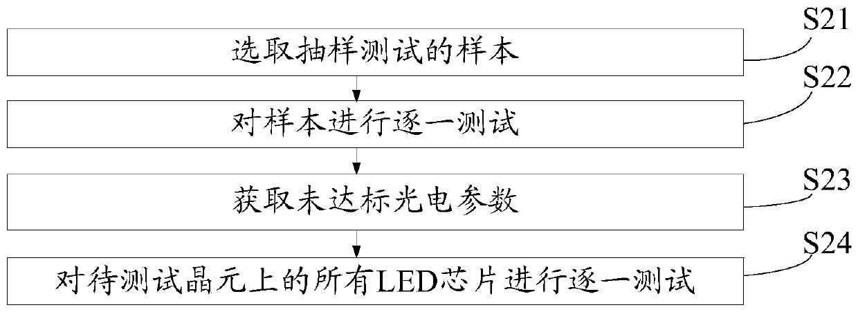
[0027] figure 1 It is a flow chart of a wafer testing method for a light-emitting diode provided by an embodiment of the present invention, such as figure 1 As shown, the test method includes:

[0028] S11: Perform a sampling test.

[0029] Specifically, a sample test is performed on the LED chips on the same wafer to be tested to obtain a sample test result, wherein the sample test result includes test results of various photoelectric parameters.

[0030] S12: Obtain photoelectric parameters that do not meet the standards.

[0031] Specifically, the sample test results are compared with corresponding preset standards of various photoelectric parameters to obtain photoelectric parameters that do not meet the standards.

[0032] S13...


PUM


Abstract

The present invention discloses a wafer test method and wafer test system for light emitting diodes and belongs to the optoelectronic technical field. The wafer test method comprises the following steps that: sampling testing is performed on LED chips on the same wafer to be tested, so that sampling testing results can be obtained; the sampling testing results are compared with the preset standards of a plurality of kinds of corresponding photoelectric parameters, so that photoelectric parameters which do not live up to the standards can be obtained; and the photoelectric parameters which do not live up to the standards of each LED chip on the same wafer to be tested are tested one by one. In a one-by-one test process, some optoelectronic parameters are not tested, and therefore, test items can be reduced, and test efficiency can be improved; and since the sampling testing has been performed, it can be ensured that untested optoelectronic parameters in the one-by-one test process can satisfy the requirements of techniques.

Description

technical field [0001] The invention relates to the field of optoelectronic technology, in particular to a wafer testing method and a wafer testing system of a light-emitting diode. Background technique [0002] Light Emitting Diode (English: Light Emitting Diode, referred to as: LED), as a very influential new product in the optoelectronics industry, has the characteristics of small size, long service life, colorful colors, and low energy consumption. It is widely used in lighting, display screens , signal lights, backlight, toys and other fields. [0003] The core structure of the LED is the LED chip. The production of the LED chip mainly includes the growth of the epitaxial wafer, the chip manufacturing and the division of the wafer. After the division of the wafer is completed, a single LED chip can be obtained. [0004] After the LED chip is manufactured, it needs to test various photoelectric parameters, and only after passing the test can it meet the needs of the mar...

Claims


Application Information

Patent Timeline
Patent Type & Authority Patents(China)
IPC IPC(8): G01R31/26G01R31/44
Inventor 喻海波叶青贤向光胜陈建南周高明
Owner HC SEMITEK ZHEJIANG CO LTD
Learn More