
A calculating method for determining the interfacial rigidity of cylinders

A calculation method and technology of interface stiffness, applied in calculation, design optimization/simulation, special data processing applications, etc., can solve problems such as large calculation error, complex finite element meshing, and low efficiency

Inactive Publication Date: 2017-09-15
NORTHEASTERN UNIV
View PDF0 Cites 3 Cited by
  • Summary
  • Abstract
  • Description
  • Claims
  • Application Information

AI Technical Summary

Problems solved by technology

[0005] In order to solve the above-mentioned problems in the prior art, the present invention provides a calculation method for determining the stiffness of the cylindrical interface, which breaks through the existing traditional Hertzian contact calculation error and finite element network for the analysis of high-precision mechanical interface contact characteristics. Due to the limitations of complex and inefficient lattice division, the results obtained by the method are accurate and reliable

Method used


Image

  • A calculating method for determining the interfacial rigidity of cylinders
  • A calculating method for determining the interfacial rigidity of cylinders
  • A calculating method for determining the interfacial rigidity of cylinders

Examples


Embodiment 1

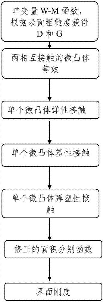
[0037] Aiming at the requirement of high-precision mechanical interface contact characteristic analysis, the present invention provides a calculation method for determining the rigidity of the cylindrical interface considering the change of material hardness with the loading depth, which is obtained according to the following steps, see figure 1 The flowchart shown:

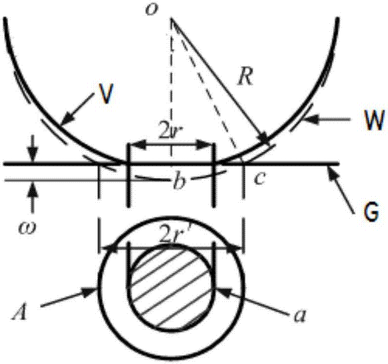
[0038] 1). With the help of the Weierstrass-Mandelbrot (W-M) function that can be used to describe the rough fractal properties of metal surfaces, According to this formula, the amount of deformation of the asperity represented by the area a and the radius of curvature at the top can be expressed as ω=G D-1 a 1-0.5D and R=π -1 G 1-D a 0.5D ; Among them, the fractal dimension of the rough surface represents the high-frequency components in the surface topography, and the range is 1a Related, according to D=1.54 / R a 0.042 Obtained, G is the fractal roughness of the rough surface, indicating the magnitude of ...

Embodiment 2

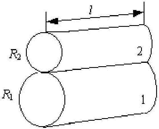
[0050] In order to verify the method of the present invention, now with Figure 5 The cylindrical junction of the combined specimens, both of which are 45 steel, is the verification object. The outer cuboid 1 is 100mm long, 72mm wide, and 84mm high; the inner cylinder 2 has a diameter of 50mm and a length of 150mm. Their materials are the same, and the specific parameters are shown in Table 1.

[0051] Table 1 Test material parameters

[0052]

[0053] According to the computing method described in embodiment 1, calculate and obtain the stiffness formula K on the total interface in step 7 n The determination of other relevant parameters in is as follows:

[0054] (1) According to step 1), D is the fractal dimension, which can be based on the relationship with surface roughness D=1.54 / R a 0.042 get, R a is the surface roughness, where the surface roughness measured by a roughness measuring instrument is 6.2, so D is 1.426.

[0055] (2) According to step 1), G is the f...


PUM

PropertyMeasurementUnit
Diameteraaaaaaaaaa
Stiffnessaaaaaaaaaa

Abstract

The invention relates to the field of dynamic analysis of mechanical interfaces and specifically relates to a calculating method for determining the interfacial rigidity of cylinders. The method specifically takes into consideration the influence of change of rigidity of contact materials along with surface loading depth, a friction coefficient in contact and elastic-plastic deformation of micro-bulges; the contact rigidity of a whole cylinder loaded interface contains elastic loads and elastic-plastic loads of all micro-bulges on the interface; the contact rigidity of cylinder interfaces is calculated by using the formula (described in the specification). The method is used for obtaining interfacial rigidity of cylinders of precision machinery. The calculating method is simple and easy to operate, enables interfacial rigidity of cylinders, which is hard to detect, to be obtained easily, overcomes the shortcomings of traditional methods, guarantees accuracy and reliability of results, and provides technical reference for controlling dynamic characteristics of cylinder interfaces.

Description

technical field [0001] The invention relates to the field of mechanical interface mechanics analysis, in particular to a calculation method for determining the rigidity of a cylinder interface. Background technique [0002] Since the interface stiffness is one of the important dynamic performance parameters of the entire mechanical system, the identification and determination of the stiffness of the cylindrical interface is conducive to accurately predicting the dynamic characteristics of the whole machine in the initial design stage of some high-precision systems, such as robots. The precision of joint precision reducer transmission directly affects the dynamic response accuracy of robot joints. Therefore, for key mechanical systems, research on typical cylindrical interface contact problems and establish an important high-precision prediction model for dynamic characteristics not only provides a basis for accuracy error compensation, but also provides technical reference f...

Claims


Application Information

Patent Timeline
IPC IPC(8): G06F17/50
CPCG06F30/17G06F30/20
Inventor 潘五九李小彭孙猛杰孙赵宁杨泽敏王琳琳
Owner NORTHEASTERN UNIV
Learn More