
Display device, array substrate and method for manufacturing array substrate

A technology of an array substrate and a manufacturing method, applied in the field of display devices, can solve the problems of pollution, poor SiNx film quality and poor isolation effect, and increasing maintenance costs.

Active Publication Date: 2021-04-23
BOE TECH GRP CO LTD
View PDF8 Cites 0 Cited by
  • Summary
  • Abstract
  • Description
  • Claims
  • Application Information

AI Technical Summary

Problems solved by technology

However, there are two problems in this solution: one is that in the related art, if the isolation layer with better isolation effect is to be formed, high-temperature deposition is required, but since the color resistance in CF is not resistant to high temperature, SiNx can only be deposited at low temperature, which leads to SiNx The film quality is loose and the isolation effect is poor, and bubbles are easy to be generated; secondly, the formation of the SiNx isolation layer requires the substrate formed with the above-mentioned CF to enter a CVD (Chemical Vapor Deposition, chemical vapor deposition) chamber for low-temperature deposition, and the color resistance in the CF may be Diffusion to the CVD chamber and causing contamination, thereby shortening the maintenance cycle of the CVD chamber, increasing maintenance costs, and affecting production capacity

Method used


Image

  • Display device, array substrate and method for manufacturing array substrate
  • Display device, array substrate and method for manufacturing array substrate
  • Display device, array substrate and method for manufacturing array substrate

Examples


Embodiment Construction

[0043] Example embodiments will now be described more fully with reference to the accompanying drawings. Example embodiments may, however, be embodied in many forms and should not be construed as limited to the examples set forth herein; rather, these embodiments are provided so that this disclosure will be thorough and complete and will fully convey the concept of example embodiments to those skilled in the art. The described features, structures, or characteristics may be combined in any suitable manner in one or more embodiments. In the following description, numerous specific details are provided in order to give a thorough understanding of embodiments of the present disclosure. However, those skilled in the art will appreciate that the technical solutions of the present disclosure may be practiced without one or more of the specific details being omitted, or other methods, components, devices, steps, etc. may be adopted. In other instances, well-known technical solution...


PUM


Abstract

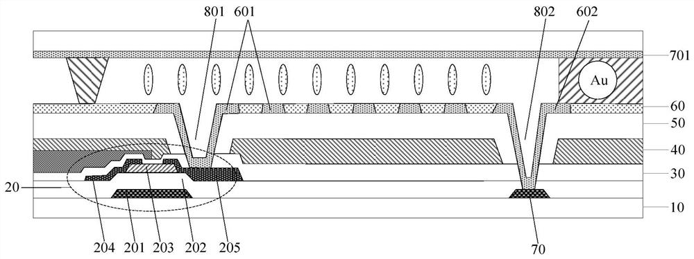
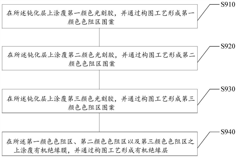
The disclosure relates to an array substrate, a manufacturing method thereof, and a display device, and relates to the technical field of liquid crystal display. The array substrate includes a base substrate, a thin film transistor layer on the base substrate, a passivation layer on the thin film transistor layer, a color resistance layer on the passivation layer, and a color resistance layer on the color resistance layer for An organic insulating layer that isolates the color resist layer. On the one hand, the present disclosure manufactures the color-resist layer in the array substrate, which can effectively solve the problems of light leakage caused by alignment deviation in the process of aligning liquid crystal display devices, thereby improving the display aperture ratio; on the other hand, the organic insulating layer is used as the The isolation layer of the color-resistive layer can improve the isolation effect, and can also avoid the formation of the isolation layer in the CVD chamber in the related art, thereby causing the diffusion of the color-resistor to contaminate the CVD chamber, thereby prolonging the maintenance period and reducing the maintenance cost.

Description

technical field [0001] The present disclosure relates to the technical field of liquid crystal display, and in particular, to an array substrate, a manufacturing method of the array substrate, and a display device including the array substrate. Background technique [0002] PSVA (Polmer Stabilized Vertically Aligned, Polymer Stabilized Vertically Aligned) mode has become the mainstream technology of LCD TVs because of its good dark state performance, high contrast, and small light leakage on curved surfaces. In order to overcome the VA (Vertivally Alignment, vertical alignment mode) viewing angle problem, people adopt designs such as 4 chips and 8 chips, which greatly improve the performance under large viewing angles. At present, PSVA has excellent dark state and curved surface light leakage performance. By designing the pixel electrode into a comb-like shape, 8 chips can be realized, which can make up for the light leakage and color distortion problems of side viewing angl...

Claims


Application Information

Patent Timeline
Patent Type & Authority Patents(China)
IPC IPC(8): H01L27/12H01L21/77
CPCH01L21/77H01L27/1248H01L27/1259
Inventor 舒适黄华柳在健
Owner BOE TECH GRP CO LTD
Learn More