Power grid state estimation method and device

A power grid state estimation and power grid technology, which is applied to circuit devices, AC network circuits, and AC networks with the same frequency from different sources, etc., can solve the problems of insufficient data utilization, increased difficulty in modeling and solving, and increased data redundancy. Redundancy and other issues

Inactive Publication Date: 2017-09-15
STATE GRID SHANDONG ELECTRIC POWER
View PDF5 Cites 3 Cited by
  • Summary
  • Abstract
  • Description
  • Claims
  • Application Information

AI Technical Summary

Problems solved by technology

[0003] The number of nodes in the PMU (Phasor Measurement Unit, power system synchrophasor measurement device, a device for measuring and outputting synchrophasor and dynamic recording) systems installed in the power grid is relatively small, and it is impossible to complete the system by using PMU data alone. state estimation, and if its data is not fully utilized, its performance improvement effect on power grid state

Method used


Image

  • Power grid state estimation method and device
  • Power grid state estimation method and device
  • Power grid state estimation method and device

Examples


Embodiment 1

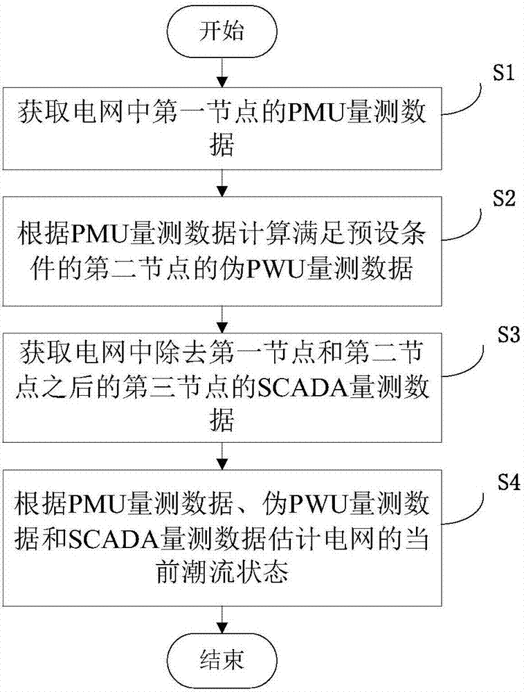
[0051] This embodiment provides a method for estimating the state of a power grid. A SCADA system is installed in the power grid. The power grid includes a first node, a second node, and a third node. The first node is equipped with a PWU device, such as figure 1 As shown, the method includes the following steps:

[0052] S1: Obtain the PMU measurement data of the first node in the power grid; here, the node where the PMU device is installed in the power grid is used as the first node. The PMU device is mainly installed in high-voltage substations and main power plants in the power grid system. For the voltage vector measurement and current vector measurement, the direct measurement of the state quantity in the state estimation is realized, and because the PMU measurement data has high accuracy, it can be considered that the PMU measurement data is the actual value to a certain extent. Realize the observability of the system part.

[0053] S2: Calculate the pseudo PWU measurement ...

Embodiment 2

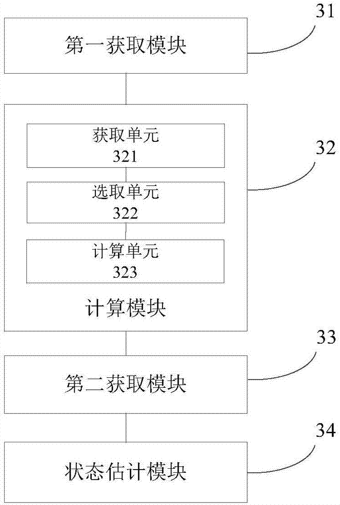
[0098] This embodiment provides a power grid state estimation device. A SCADA system is installed in the power grid. The power grid includes a first node, a second node, and a third node. The first node is equipped with a PWU device, such as image 3 As shown, the device includes: a first acquisition module 31, a calculation module 32, a second acquisition module 33, and a state estimation module 34. The main functions of each module are as follows:

[0099] The first obtaining module 31 is configured to obtain PMU measurement data of the first node in the power grid. For details, refer to the detailed description of step S1 in Embodiment 1.

[0100] The calculation module 32 is configured to calculate pseudo PWU measurement data of the second node that meets the preset condition according to the PMU measurement data. For details, refer to the detailed description of step S2 in Embodiment 1.

[0101] The second acquiring module 33 is used to acquire the SCADA measurement data of the...


PUM


Abstract

The invention provides a power grid state estimation method and device. A power grid comprises a first node, a second node and a third node, a PWU device is installed in the first node, and the method comprises the following steps: obtaining PMU measurement data of the first node in the power grid; calculating pseudo PMU measurement data of the second node satisfying a preset condition according to the PMU measurement data; obtaining SCADA measurement data of the third node in the power grid excluding the first node and the second node; and estimating a tidal current state of the power grid at present according to the PMU measurement data, the pseudo PMU measurement data and the SCADA measurement data. The technical scheme makes full use of the PMU measurement data and the SCADA measurement data, reduces the matrix dimensions in a power grid state estimation process, the modeling complexity and the solution difficulty through power grid decomposition and coordination calculation, and improves the power grid state estimation efficiency.

Description

Technical field [0001] The present invention relates to the field of power grid management, in particular to a method and device for estimating power grid state. Background technique [0002] In recent years, with the continuous improvement of the level of power grid digitalization and power dispatch automation, rich information can be transmitted to dispatch centers at all levels in real-time or quasi-real-time, which makes it possible to comprehensively use collected real-time information to evaluate the operation status of the power grid , Based on accurate grid state assessment and finally used in the prediction of system state transition, to achieve a panoramic grasp of the safety and stability level of grid operation, dispatch adjustment ability and the ability of the grid to resist risks. Realize timely prevention and control of weak links in the safe operation of the power grid, and reduce the risk of power grid operation. [0003] PMU (Phasor Measurement Unit, power syste...

Claims


Application Information

Patent Timeline
IPC IPC(8): H02J3/06
CPCH02J3/06H02J2203/20
Inventor 撖奥洋于立涛张滨孙忠良钟世民李辰王强周生奇王黎陈胜张陶
Owner STATE GRID SHANDONG ELECTRIC POWER
Why Eureka
Try Eureka