Base station monitoring method for realizing alarm based on database trigger

A database and trigger technology, applied in database design/maintenance, data exchange network, structured data retrieval, etc., can solve problems such as increasing difficulty, large differences in base station monitoring data, and difficulty in implementation, making it easy to check and fill gaps, and can The effect of strong maintenance and strong maintenance

Inactive Publication Date: 2017-09-15
UNIV OF ELECTRONICS SCI & TECH OF CHINA
View PDF2 Cites 3 Cited by
  • Summary
  • Abstract
  • Description
  • Claims
  • Application Information

AI Technical Summary

Problems solved by technology

However, when the traditional monitoring method is applied to the base station monitoring system, it is found that this solution is difficult to implement. The main problem is that the amount of data monitored by the base station is much larger than that of the general embedded monitoring system, and the monitoring equipment mounted on different base stations is also different. Therefore, the monitoring data of different base stations are also quite different
When using the traditional monitoring method, it is necessary to judge and process each piece of data inside the program. Once the requirements change, such as the monitoring system is connected to a new monitoring device, the amount of monitoring data in the base station increases. Corresponding to the source code, it

Method used


Image

  • Base station monitoring method for realizing alarm based on database trigger
  • Base station monitoring method for realizing alarm based on database trigger
  • Base station monitoring method for realizing alarm based on database trigger

Examples


Embodiment Construction

[0017] The scheme of the present invention will be further described in detail below in conjunction with the accompanying drawings and specific implementation examples, so that those skilled in the art can better understand the present invention and implement it, but the example given here is only an implementation of the present invention. The specific implementation can have more choices.

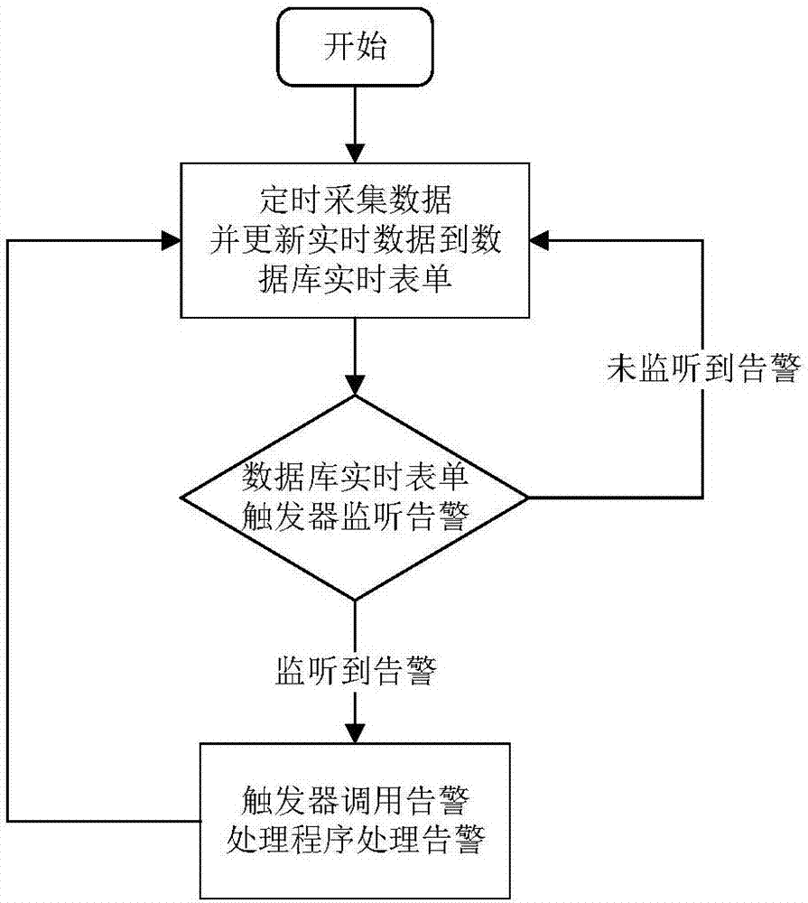
[0018] In the present invention, the collection frequency of different detection objects can be distinguished. For example, slow-changing signals such as temperature and humidity can be collected once every half an hour; signals that may change instantaneously such as infrared and smoke senses can be collected at least once every 30 seconds. Design alarm rules for different detection objects. For example, for alarms triggered by Boolean signals such as infrared and smoke, these signals have only two values. Generally, the value of normal conditions is defined as 0, and the value of abnorma...


PUM


Abstract

The invention belongs to the field of a monitoring system and provides a base station monitoring method for realizing alarm based on a database trigger. The method is used for improving the expansibility and maintainability of a base station monitoring system and reducing system development and debugging workloads and the system development difficulty. The method comprises the steps of setting a database, wherein items of the database comprise monitoring objects, real-time monitoring values, a monitoring value upper limit and a monitoring value lower limit, and setting a trigger for each detection object; collecting the real-time monitoring values of base stations through sensors and storing the real-time monitoring values to the database in real time; checking the real-time monitoring values by the database through the triggers, calling an alarm processing program when the real-time monitoring values exceed the monitoring value upper limit or the monitoring value lower limit; and uploading alarm information comprising the current detection objects and the real-time monitoring values to a monitoring center by the alarm processing program. The base station monitoring method provided by the invention has the advantages of high expansibility, high maintainability and convenient management.

Description

technical field [0001] The invention belongs to the field of monitoring systems, in particular to a base station monitoring method for realizing alarm based on a database trigger. Background technique [0002] In recent years, in order to meet the needs of the masses for mobile communications, the number of base stations has continued to increase. In order to ensure the stable operation of base stations, the country has invested a lot of manpower and material resources in the development of base station monitoring systems. Currently, base station monitoring is characterized by a large amount of data; in general, base station monitoring objects include environmental information (humidity, temperature, water immersion, door contact, infrared, smoke, vibration, etc.) and power information (battery packs, switching power supplies, Smart air conditioners, heat exchange equipment, smart access control, etc.), the accumulation of these data will make the amount of information monit...

Claims


Application Information

Patent Timeline
IPC IPC(8): H04W24/04H04W24/08H04L12/24H04L12/26G06F17/30
CPCG06F16/21H04L41/06H04L43/08H04W24/04H04W24/08
Inventor 侯晓荣陈刚郭聪樊建峰
Owner UNIV OF ELECTRONICS SCI & TECH OF CHINA
Why Eureka
Try Eureka