
Control circuit and lighting device

A technology of control circuit and operational amplifier circuit, which is applied in the field of lighting, can solve the problems of affecting circuit operation, limiting the dimming range of the circuit, and reducing the output current and the first output signal proportionally, etc.

Active Publication Date: 2017-09-15
OPPLE LIGHTING
View PDF10 Cites 7 Cited by
  • Summary
  • Abstract
  • Description
  • Claims
  • Application Information

AI Technical Summary

Problems solved by technology

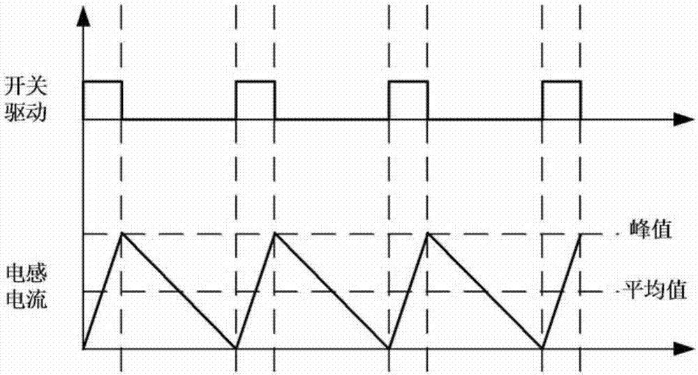
[0003] However, the step-down circuit works in critical current mode, and its operating frequency varies with the input voltage and load. As the dimming depth increases, the operating frequency of the step-down circuit also increases. When the operating frequency is high enough, The signal delay generated by the control circuit will greatly affect the operation of the circuit. The inductor current is no longer a critical operating mode, and the peak value of the current is no longer linearly proportional to the average value. The output current cannot be further reduced in proportion to the first output signal, thus limiting The dimming range of the circuit

Method used


Image

  • Control circuit and lighting device
  • Control circuit and lighting device
  • Control circuit and lighting device

Examples


Embodiment Construction

[0069] Exemplary embodiments of the present disclosure will be described in more detail below with reference to the accompanying drawings. Although exemplary embodiments of the present disclosure are shown in the drawings, it should be understood that the present disclosure may be embodied in various forms and should not be limited by the embodiments set forth herein. Rather, these embodiments are provided for more thorough understanding of the present disclosure and to fully convey the scope of the present disclosure to those skilled in the art.

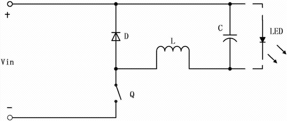
[0070] figure 1 It shows a schematic diagram of a step-down circuit, where Q is a switching device, D is a freewheeling diode, L is an inductor, and the output electrolytic capacitor C is connected in parallel with the load LED. The inductor L and the electrolytic capacitor C are mainly used to filter out the high-frequency switching power supply noise, ensuring the output is a low ripple DC current.

[0071] LED is a current-driv...


PUM


Abstract

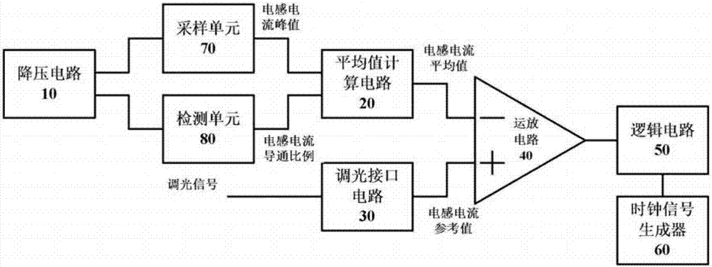
The invention provides a control circuit and a lighting device. The control circuit comprises a step-down circuit, a mean value calculation circuit, a light dimming interface circuit, an operational amplifier circuit, a logic circuit, a clock signal generator, a sampling unit and a detection unit. The mean value calculation circuit calculates an inductive current mean value based on the inductive current peak value and the inductive current conduction ratio. The operational amplifier circuit performs comparison based on the inductive current mean value and the inductive current reference value inputted by the light dimming interface circuit, and the comparison result acts as a first output signal to be outputted to the logic circuit. The logic circuit controls on / off of the first switch in the step-down circuit based on the first output signal and the clock signal inputted by the clock signal generator and adjusts the size of the inductive current by controlling the duty ratio of the first switch in the step-down circuit so as to adjust the current size of a load connected with the electric inductor. The control circuit is simple and convenient, and the lighting device provided with the control circuit has wide light dimming range and low cost.

Description

technical field [0001] The invention relates to the lighting field, in particular to a control circuit and a lighting device. Background technique [0002] At present, the step-down circuit is more and more widely used in the LED drive circuit because of its small number of components and high conversion efficiency, and it is suitable for converting from high-voltage input to low-voltage output. [0003] However, the step-down circuit works in critical current mode, and its operating frequency varies with the input voltage and load. As the dimming depth increases, the operating frequency of the step-down circuit also increases. When the operating frequency is high enough, The signal delay generated by the control circuit will greatly affect the operation of the circuit. The inductor current is no longer a critical operating mode, and the peak value of the current is no longer linearly proportional to the average value. The output current cannot be further reduced in proporti...

Claims


Application Information

Patent Timeline
Patent Type & Authority Applications(China)
IPC IPC(8): H05B33/08H05B44/00
CPCH05B45/00H05B45/10Y02B20/40
Inventor 文威
Owner OPPLE LIGHTING
Learn More