Evaporating pipe and spraying device

A spray device and evaporation tube technology, applied in the field of evaporation tubes, can solve the problems of poor uniformity of the oil mist field in the combustion chamber, and achieve the effects of avoiding adverse effects, uniform distribution of oil mist, and strengthening the degree of oil-gas premixing

Active Publication Date: 2017-09-19
AECC HUNAN AVIATION POWERPLANT RES INST
View PDF5 Cites 12 Cited by
  • Summary
  • Abstract
  • Description
  • Claims
  • Application Information

AI Technical Summary

Problems solved by technology

[0003] The invention provides an evaporation tube and a spray device to solve the technical problem of poor uniformity of the oil mist field in the combustion chamber

Method used


Image

  • Evaporating pipe and spraying device
  • Evaporating pipe and spraying device
  • Evaporating pipe and spraying device

Examples


Embodiment Construction

[0025] The embodiments of the present invention will be described in detail below with reference to the accompanying drawings, but the present invention can be implemented in many different ways defined and covered by the claims.

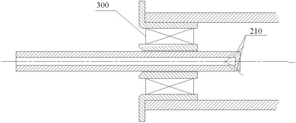
[0026] refer to image 3 and 4 , the preferred embodiment of the present invention provides an evaporator tube 100, the fuel nozzle 200 extends from the inlet end of the evaporator tube 100, and the feature is that the inlet end of the evaporator tube 100 is provided with a The air of the swirler 300 is converted into a swirling airflow swirler 300, the swirler 300 is set between the evaporation tube 100 and the fuel nozzle 200, and the swirler 300 is located in the behind the nozzle 210 of the fuel nozzle 200, so that the fuel sprayed from the nozzle and the swirling airflow form an atomized fuel-air mixture.

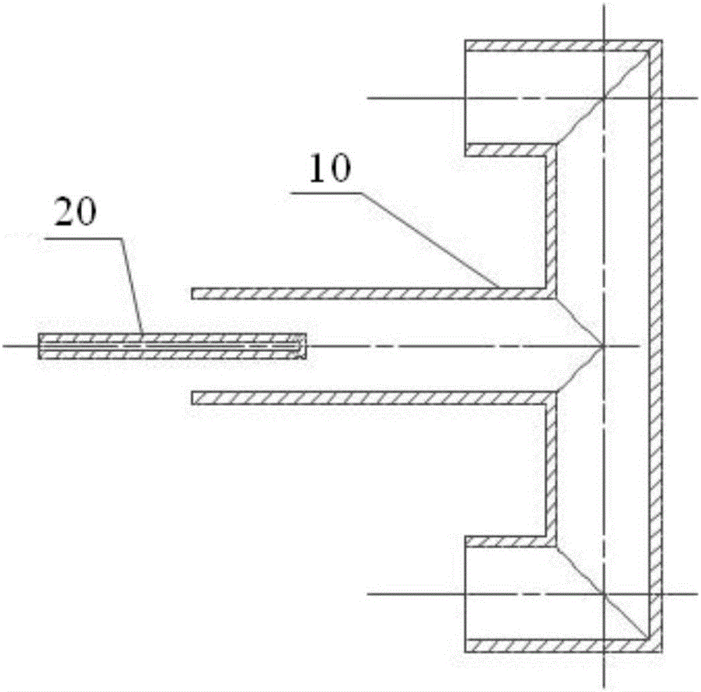
[0027] The inventors found that, with reference to figure 1 , 2 and 6, in the design of the conventional evaporator tube 10, the advers...


PUM


Abstract

The invention discloses an evaporating pipe. A fuel oil nozzle extends in from the inlet end of the evaporating pipe. The inlet end of the evaporating pipe is provided with a cyclone used for converting air flowing through the cyclone into rotary airflow. The cyclone is arranged between the evaporating pipe and the fuel oil nozzle and is located behind a spray opening of the fuel oil nozzle. An inlet of the evaporating pipe is provided with the cyclone, thus airflow in the evaporating pipe changes from non-prewhirl high-speed airflow into the rotary airflow. The rotary airflow can effectively reinforce the oil and gas premixing degree, the adverse impact caused by the difference of fuel oil flow of the spray opening of the fuel oil nozzle matched with the evaporating pipe in long-term work is avoided effectively, meanwhile, the rotary airflow can prolong the residence time of an oil and gas mixture in the evaporating pipe, then the time of oil and gas mixing is prolonged, the heat exchange area of the oil and gas mixture and the evaporating pipe wall is enlarged, the fuel oil atomization-evaporation rate is increased substantially through the high-temperature evaporating pipe, thus oil mist at an outlet of the evaporating pipe is distributed more evenly, and the performance of a combustor is ensured.

Description

technical field [0001] The invention relates to the field of spray devices, in particular to an evaporation tube. In addition, the present invention also relates to a spraying device comprising the above-mentioned evaporating tube. Background technique [0002] As a spray device in the combustion chamber, the evaporator tube uses the air in the tube to promote the atomization of the fuel, and increases the evaporation of the fuel with the help of the high inlet air temperature and the high-temperature main combustion zone to improve the combustion performance. The typical structure of the evaporator tube is Volute shape, "Γ" shape and "T" shape, the current mainstream design of the evaporator tube type combustor mostly adopts "T" shape evaporator tube. refer to figure 1 and 2 , the evaporator tube 10 mostly adopts a direct injection nozzle 20, and the fuel is directly injected through one or several small hole nozzles 21, such as figure 1 As shown, when the number of noz...

Claims


Application Information

Patent Timeline
Patent Type & Authority Applications(China)
IPC IPC(8): F23R3/32
CPCF23R3/32
Inventor 徐艳冰王利邬俊王倚阳
Owner AECC HUNAN AVIATION POWERPLANT RES INST
Why Eureka
Try Eureka