DC-DC LED driving circuit based on PWM dimming
A driving circuit and dimming technology, applied in the direction of light source, electric light source, electrical components, etc., can solve problems such as LED damage, capacitor noise, etc., achieve good linearity, eliminate overshoot current, and fast settling speed
- Summary
- Abstract
- Description
- Claims
- Application Information
AI Technical Summary
Problems solved by technology
Method used
Image

Examples
Embodiment Construction
[0037] The above and / or additional aspects and advantages of the present invention will become apparent and comprehensible from the following description of the embodiments in conjunction with the accompanying drawings.
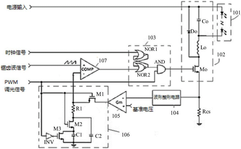
[0038] image 3 It shows a BUCK type DC-DC LED drive circuit based on PWM dimming in the present invention, including LED load 101, DC-DC conversion circuit 102, logic circuit 103, error amplifier 105, compensation circuit 106, and duty cycle signal generation circuit 107 and the current sampling resistor Rcs. Each component in this embodiment is described in detail below:
[0039] The compensation circuit 106 is the core of the present invention, which includes: a frequency compensation resistor R1, one end of which is connected to the duty cycle signal generating circuit 107; a first switching tube M1, whose gate is connected to a PWM dimming signal end to receive a PWM For the dimming signal, the drain is connected to the output terminal of the error amp...
PUM
 Abstract
Description
Claims
Application Information
 - Generate Ideas
- Intellectual Property
- Life Sciences
- Materials
- Tech Scout
- Unparalleled Data Quality
- Higher Quality Content
- 60% Fewer Hallucinations
Browse by: Latest US Patents, China's latest patents, Technical Efficacy Thesaurus, Application Domain, Technology Topic, Popular Technical Reports.
© 2025 PatSnap. All rights reserved.Legal|Privacy policy|Modern Slavery Act Transparency Statement|Sitemap|About US| Contact US: help@patsnap.com