Knee joint spreader

A knee joint and spreader technology, applied in the field of medical devices, can solve problems such as bone defects, inability to parallelly spread the femoro-tibial gap, and indentation at the contact position, so as to reduce injuries, facilitate subsequent recovery, and be safe and reliable in use Effect

Inactive Publication Date: 2017-09-22
BEIJING CHUNLIZHENGDA MEDICAL INSTR
View PDF6 Cites 2 Cited by
  • Summary
  • Abstract
  • Description
  • Claims
  • Application Information

AI Technical Summary

Problems solved by technology

However, due to the limitation of its structure, the knee joint spreader 10 in the prior art cannot parallelly spread the femorotibial space when stretching, which will cause pressure on the contact position between the two support plates (1011, 1021) and the bone surface. scars, causing minor bone defects

Method used


Image

  • Knee joint spreader
  • Knee joint spreader
  • Knee joint spreader

Examples


Embodiment Construction

[0022] Embodiments of the technical solutions of the present invention will be described in detail below in conjunction with the accompanying drawings. The following examples are only used to illustrate the technical solutions of the present invention more clearly, and therefore are only examples, rather than limiting the protection scope of the present invention.

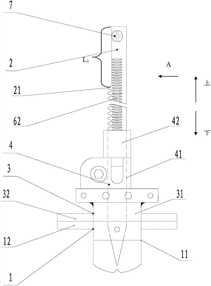
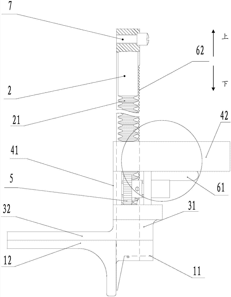
[0023] figure 2 It is the front view of the knee joint spreader according to the embodiment of the present invention, image 3 for figure 2 Side view of the knee spreader shown. Such as figure 2 and image 3 As shown, the knee spreader includes a lower brace 1, a guide rod 2, an upper brace 3, a support member 4, a gear 5 and a rack structure 21 arranged on the guide rod. The guide rod 2 is vertically arranged on the upper part of the lower support plate 1 , and the rack structure 21 extends along the longitudinal direction of the guide rod 2 . The cross-section of the guide rod 2 is preferably polygonal, ...


PUM


Abstract

The invention relates to a knee joint spreader. The knee joint spreader comprises a lower spreading plate, a guide rod, a gear rack structure, an upper spreading plate and a gear, wherein the guide rod is vertically arranged on the upper portion of the lower spreading plate, the gear rack structure is arranged on the guide rod and extends in the longitudinal direction of the guide rod, the upper spreading plate is arranged on the guide rod in a sleeving mode and is parallel to the lower spreading plate, the gear is arranged on the upper portion of the upper spreading plate through a support component, and the gear is rotatably arranged on the support component and can be meshed with the gear rack structure; when the gear rotates on the gear structure to force the upper spreading plate to slide upwards along the guide rod, the upper spreading plate gradually gets away from the lower spreading plate; when the gear rotates on the gear structure to force the upper spreading plate to slide downwards along the guide rod, the upper spreading plate gradually gets close to the lower spreading plate. By the adoption of the knee joint spreader, the gap between the femoral tibias can be spread in a parallel mode to reduce the possibility of bone defects of a patient caused by knee arthroplasty.

Description

technical field [0001] The invention belongs to the field of medical equipment, in particular to a knee joint spreader. Background technique [0002] Knee spreader is a commonly used orthopedic medical device in knee joint resurfacing surgery, which is used to open the femorotibial space of the knee joint. The structure of the knee joint spreader in the prior art is as figure 1 As shown, the knee joint spreader 10 is a pliers hinge structure, which includes a left pliers handle 101 and a right pliers handle 102 hinged with the left pliers handle 101, and the heads of the left pliers handle 101 and the right pliers handle 102 are fixedly connected with For the support plate (1011, 1021), a spring assembly 103 is provided between the left handle 101 and the right handle 102, and a lock assembly 104 is provided between the tail of the left handle 101 and the tail of the right handle 102. In actual use, external force acts on the left and right pliers handles (101, 102), so th...

Claims


Application Information

Patent Timeline
Patent Type & Authority Applications(China)
IPC IPC(8): A61B17/88
CPCA61B17/885
Inventor 史春宝吕昌禹解凤宝
Owner BEIJING CHUNLIZHENGDA MEDICAL INSTR
Why Eureka
Try Eureka