Reverse artificial shoulder prosthesis

A joint prosthesis and artificial shoulder technology, applied in the direction of shoulder joints, prostheses, joint implants, etc., can solve the problems of patients with unstable joint function recovery, insufficient external movement of the humeral head, and reduced force transmission. Achieve the effect of reducing impact on the subglenoid notch, facilitating operation, and large descending space

Inactive Publication Date: 2017-09-22
BEIJING CHUNLIZHENGDA MEDICAL INSTR
View PDF8 Cites 5 Cited by
  • Summary
  • Abstract
  • Description
  • Claims
  • Application Information

AI Technical Summary

Problems solved by technology

[0005] 3) It is impossible to completely avoid the impingement of the humerus lining on the subglenoid notch, there is a chance of impacting on the subglenoid notch, and there is a chance of glenoid loosening during normal postoperative activities;
[0006] 4) Surface spraying is really helpful for bone ingrowth, but the transmission of force has not been reduced. All the stress on the prosthesis during human activities will be transmitted to the host bone without reservation, and the prosthesis will loosen in the long run
[0007] The reverse shoulder joint at the present stage still has the problem of unstable joint function recovery after surgery. Since the glenoid component of the current reverse shoulder joint ignores the problem of osteoporosis after implantation, when the glenoid disc is installed under pressure, use Submergence of the contact surface of the glenoid disc into the host bone, resulting in insufficient abduction of the humeral head
The eccentricity of the downward movement of the shoulder glenoid components depends entirely on the doctor's experience. The current structure has a limited downward movement range, which may still impinge on the lower notch of the glenoid after surgery, and the intraoperative operation is very limited.

Method used


Image

  • Reverse artificial shoulder prosthesis
  • Reverse artificial shoulder prosthesis
  • Reverse artificial shoulder prosthesis

Examples


Embodiment Construction

[0032] In order to better understand the purpose, structure and function of the present invention, the reverse artificial shoulder joint prosthesis of the present invention will be further described in detail below in conjunction with the accompanying drawings.

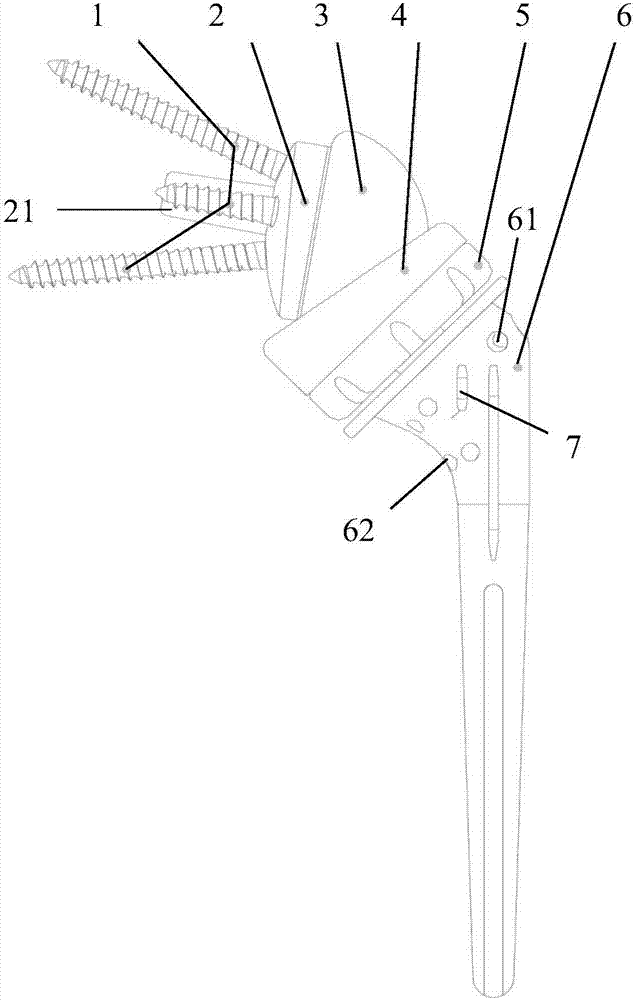
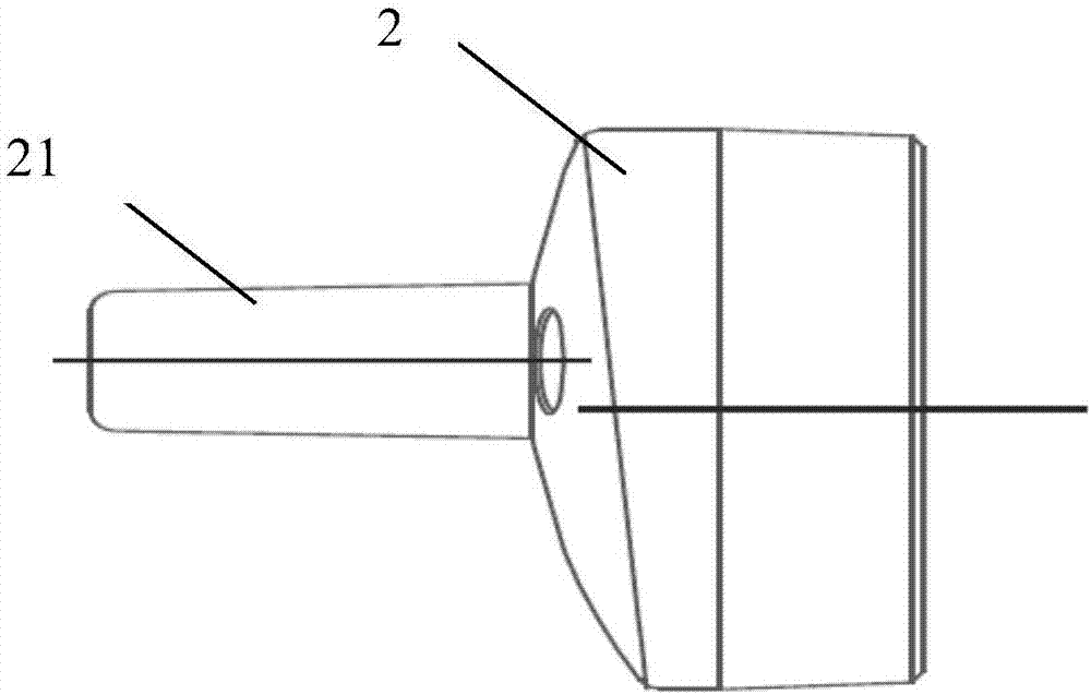
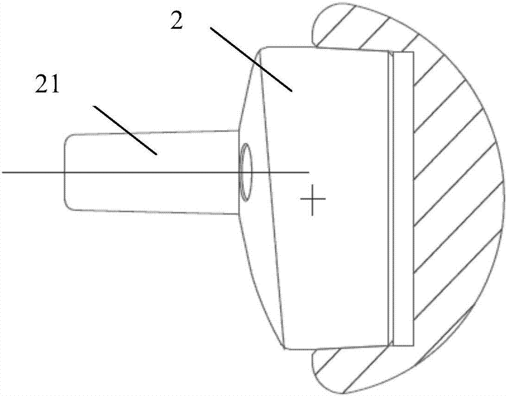
[0033] Such as figure 1 As shown, it is shown as a reverse artificial shoulder joint prosthesis of the present invention, including a glenoid disc 2, a side of the glenoid disc 2 is provided with a plurality of screws 1 for inserting into the scapula, and the glenoid disc 2 is fixed by bolts Screw 1; the other end is connected with the humerus component, the humerus component includes the humeral head 3, the humeral lining 4, the humeral disc 5 and the humeral stem 6, the humeral head 3 is connected with the glenoid disc 2; the humeral lining 4 is used on the side close to the humeral head 3 To accommodate the humeral head 3, the humeral head 3 and the glenoid disc 2 rotate in the humeral lining 4; the side of the hum...


PUM


Abstract

The invention discloses a reverse artificial shoulder prosthesis. The reverse artificial shoulder prosthesis includes a shoulder glenoid cavity (2), wherein multiple bolts (1) for being inserted into the shoulder blade are mounted at one side of the shoulder glenoid cavity (2); the other end of the shoulder glenoid cavity (2) is connected to a humerus assembly. The humerus assembly includes a humerus head (3), a humerus lining (4), a humerus plate (5) and a humerus handle (6), wherein the humerus head (3) is connected with the shoulder glenoid cavity (2), the side, near to the humerus head (3), of the humerus lining (4) is used for containing the humerus head (3), the humerus head (3) and the shoulder glenoid cavity (2) can rotate in the humerus lining (4), the side, near the humerus lining (4), of the humerus plate (5) is connected to the the humerus lining (4) in a locking mode, the proximal end of the humerus handle is connected to the humerus plate (5), the transverse section of the proximal end of the humerus handle is elliptic, and the distal end of the humerus handle is used for being implanted in the proximal end of a humeral medullary cavity. The reverse artificial shoulder prosthesis can keep not loose during long-term use and meanwhile reduce the impact of an inferior glenohumeral notch.

Description

technical field [0001] The invention relates to a medical prosthesis, in particular to a reverse artificial shoulder joint prosthesis. Background technique [0002] The reverse shoulder joint is used for joint replacement of shoulder joints with large rotator cuff injuries, shoulder fractures, and tumor shoulder joints. The reverse shoulder joint at this stage has been able to complete the surgical replacement very well, but its structure has been found in actual use. There are still some shortcomings, which cause this kind of reverse shoulder joint to fail to achieve the best use effect in practical applications, and its shortcomings can be summarized as follows: [0003] 1) Neglecting the natural shape of the proximal end of the medullary cavity, resulting in unnecessary damage to the patient's bone in actual use, or the risk of postoperative rotational loosening under the condition of external force; [0004] 2) The threaded fixation of the humeral lining and the humeral...

Claims


Application Information

Patent Timeline
Patent Type & Authority Applications(China)
IPC IPC(8): A61F2/40
CPCA61F2/40A61F2/4014A61F2/4059A61F2002/30339A61F2002/4011A61F2002/4018
Inventor 王黎明姚庆强解凤宝郭静
Owner BEIJING CHUNLIZHENGDA MEDICAL INSTR
Why Eureka
Try Eureka