New-concept railway safety dead end

A technology of railway safety and new concept, applied in the field of the end line, can solve the problems of long occupied track length, poor vehicle adaptability, complex structure, etc., and achieve the effect of short length, strong adaptability and simple structure

Inactive Publication Date: 2017-09-22
徐玉林
View PDF0 Cites 2 Cited by
  • Summary
  • Abstract
  • Description
  • Claims
  • Application Information

AI Technical Summary

Problems solved by technology

[0002] There are many dead lines in my country's railways. At present, in order to prevent derailment accidents caused by vehicles rushing out of the dead line, most of them adopt methods such as installing car stoppers and dampers at the dead ends. The disadvantages of this method are large volume, complex structure, and long track length. Poor adaptability to vehicles of different weights and speeds

Method used


Image

  • New-concept railway safety dead end
  • New-concept railway safety dead end
  • New-concept railway safety dead end

Examples


Embodiment 1

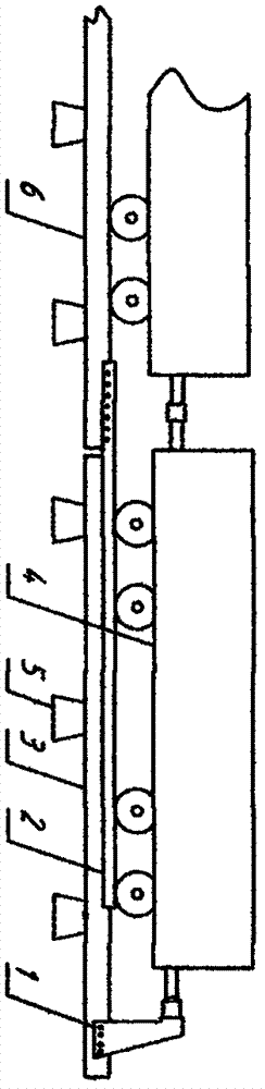
[0012] The structure of the first embodiment is as attached figure 2 As shown, the arresting pile 1 is connected to the moving rail 3, one end of the rail bridge 2 is connected to the static rail 6, and the other end and the moving rail 3 are in contact with each other, and can slide relative to each other and are attached to each other in parallel.

[0013] The working principle is that when the vehicle 4 collides with the arresting pile 1, the arresting pile 1 will drive the moving rail 3 to move together with the vehicle 4. The upper part of the moving rail 3 carries the gravity of the vehicle 4, and the lower part is the sleeper 5, so when the moving rail 3 When sliding on the sleeper 5, there will be a great frictional resistance, and this resistance will in turn be transmitted to the vehicle 4 through the blocking pile 1, causing the vehicle 4 to decelerate and stop quickly, avoiding the occurrence of derailment accidents. The main function of the rail bridge 2 is to ac...

Embodiment 2

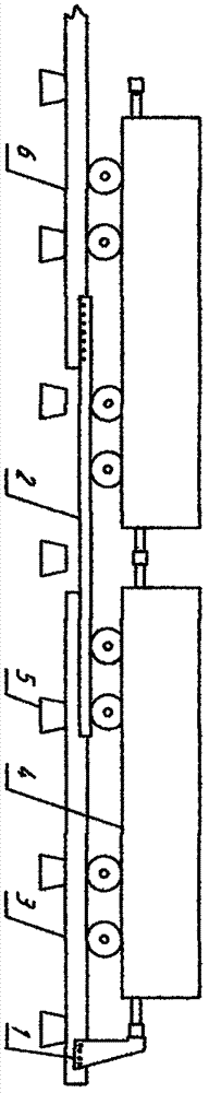
[0014] The structure of the second embodiment is as attached image 3 As shown, the arresting pile 1 is connected to the moving rail 3, one end of the rail bridge 2 is connected to the moving rail 3, and the other end and the static rail 6 not only contact each other, but also slide relative to each other, and abut against each other in parallel.

[0015] The working principle is the same as that of the first embodiment.

Embodiment 3

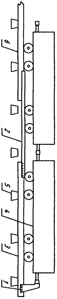
[0016] The structure of the third embodiment is as attached Figure 4 As shown, the arresting pile 1 is connected to the moving rail 3, and the rail bridge 2 is fixedly installed on the sleeper 5, and abuts against the moving rail 3 and the static rail 6 in parallel with each other, respectively.

[0017] The working principle is the same as that of the first embodiment.


PUM


Abstract

The invention relates to the dead line in the railway line, especially the dead end of the dead line, which is a new concept railway safety dead end which can prevent vehicles from rushing out of the dead line and avoid derailment accidents. The technical solution and principle are that the arresting pile (1) is connected to the moving rail (3), and when the vehicle (4) collides with the arresting pile (1), it will drive the moving rail (3) to move together with the vehicle (4), and the rail bridge ( 2) It can bear the load between the moving rail (3) and the static rail (6), and the frictional resistance received by the moving rail (3) when it slides on the sleeper (5) can cause the vehicle (4) to decelerate and stop quickly, Avoid derailment accidents.

Description

technical field [0001] The invention relates to the end line in the railway line, especially the end line of the end line, which is a new concept of railway safety end that can prevent vehicles from rushing out of the end line and avoid derailment accidents. Background technique [0002] There are many end lines of railways in my country. At present, in order to prevent vehicles from rushing out of the end line and derailing accidents, most of the methods are used to install stoppers and dampers at the end. The disadvantages of this method are large volume, complex structure and long track length. Poor adaptability to vehicles of different weights and speeds. SUMMARY OF THE INVENTION [0003] In the present invention, the pair of short rails at the end of the end line are called "moving rails", and the other steel rails are called "static rails"; the technical solution is to disconnect the connection between the moving rails and the static rails, and install blocking at the...

Claims


Application Information

Patent Timeline
Patent Type & Authority Applications(China)
IPC IPC(8): B61K7/16B61H11/16
CPCB61K7/16B61H11/16
Inventor 关树林
Owner 徐玉林
Why Eureka
Try Eureka