
A parallel clamping device for clamping small parts

A technology of parallel clamps and parts, applied in conveyor objects, transportation and packaging, metal processing equipment, etc., can solve the problems of low precision of clamping devices, unsuitable for small assembly environments, single assembly type, etc., and achieves novel design ideas, Solve the effect of smooth transition and ensure stability

Active Publication Date: 2019-02-12
ZHEJIANG UNIV OF TECH
View PDF9 Cites 0 Cited by
  • Summary
  • Abstract
  • Description
  • Claims
  • Application Information

AI Technical Summary

Problems solved by technology

[0008] In order to overcome the shortcomings of the existing clamping device, such as low precision, unsuitability for small assembly environments, and single assembly types, the present invention provides a clamp with high precision, effective for small parts clamping and assembly environments, and good versatility. Parallel clamping device for holding small parts

Method used


Image

  • A parallel clamping device for clamping small parts
  • A parallel clamping device for clamping small parts
  • A parallel clamping device for clamping small parts

Examples


Embodiment Construction

[0034] The present invention will be further described below in conjunction with the accompanying drawings.

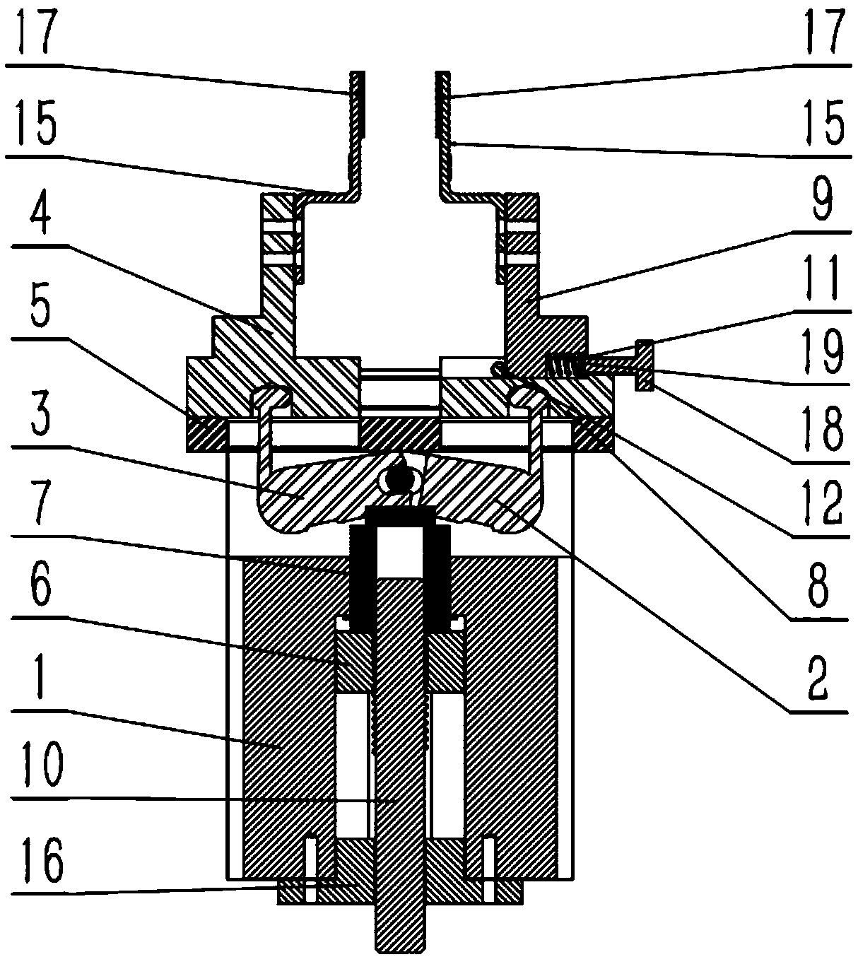
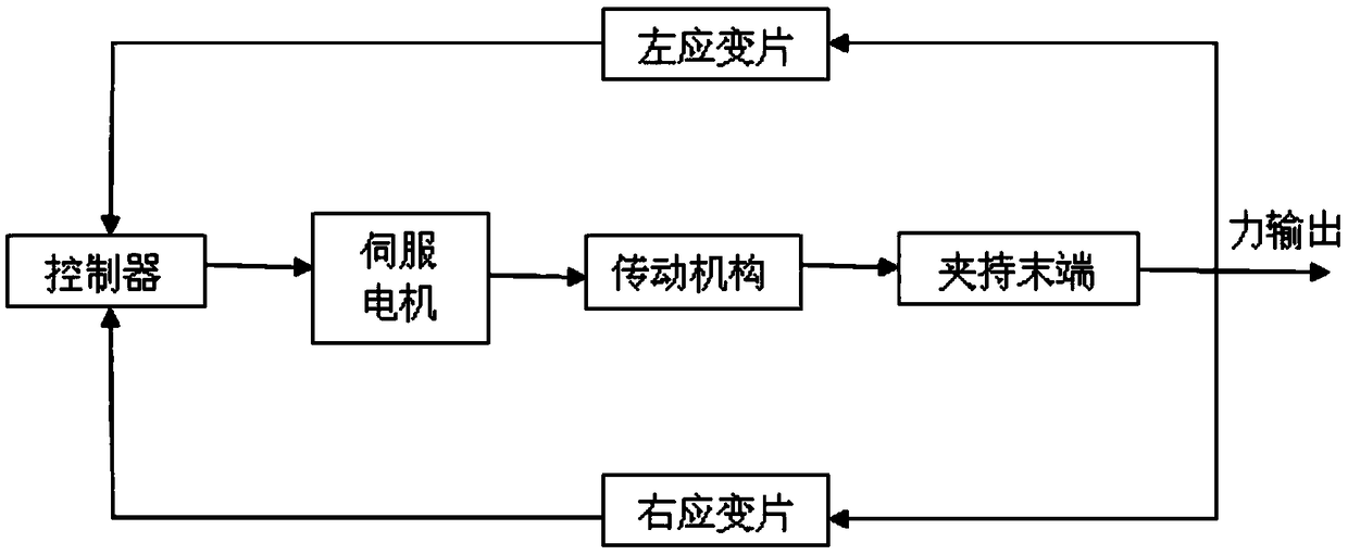
[0035] refer to Figure 1 to Figure 9 , a parallel clamping device for clamping small parts, including: a screw nut transmission part 1 used to transmit the motion of the servo motor, a transmission part 2 used to convert the nut rotation motion into the clamp parallel motion, and used to perform output The clamping end and the flexible clamp part 3 as a control clamping force.

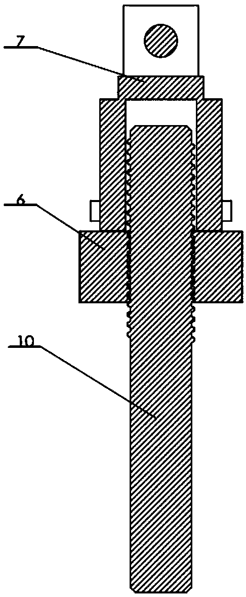
[0036] Wherein, the transmission part 1 includes: as image 3 As shown, the lead screw 10 is used to connect the servo motor. The lead screw 10 is connected to the nut 6 through threads. One end of the lead screw 10 is placed on the bearing seat 16 installed in the box body 1, and the nut 6 is in the chute inside the box body 1. The inside can only move up and down in parallel, so that the screw nut mechanism can work normally and with high precision in the absence of a bearing. The upper pa...


PUM


Abstract

A parallel clamping device for clamping small components comprises a transmission part used for converting the rotation movement of a motor into the parallel movement of a clamp, a clamping tail end used for executing output, and a flexible clamp part serving as control clamping force. The action end of the transmission part is connected with the flexible clamp part. The flexible clamp part comprises a rigidity clamp body and a soft clamp body which are symmetrically arranged. The soft clamp body comprises a base, a spring, a spring adjusting rotary knob, a spring adjusting piece, a positioning pin and an upper part. A sliding groove is formed in the base. The upper part is located in the sliding groove in a sliding manner. The positioning pin is arranged in the sliding groove. The positioning pin is located on one side of the upper part. The other side of the upper part abuts against one end of the spring. The other end of the spring is arranged on the spring adjusting piece. The action end of the spring adjusting rotary knob abuts against the spring adjusting piece. The clamping tail end is located on the upper part. The parallel clamping device is high in precision, effectively suitable for the small component clamping assembling environment and good in universality.

Description

technical field [0001] The invention relates to a clamping device, in particular to a parallel clamping device for clamping small parts for assembly in a small space. Background technique [0002] In industrial production, manipulator grippers are widely used. The manipulator hand is a part used to grasp the workpiece (or tool), and has various structural forms, such as clamping type, holding type and adsorption type. The types of manipulators can be divided into hydraulic, pneumatic, electric and mechanical manipulators according to the driving mode; they can be divided into special manipulators and general manipulators according to the scope of application; they can be divided into point control and continuous manipulators according to the motion trajectory control mode. Trajectory control manipulator, etc. [0003] Now it has entered the era marked by universal manipulators. Due to the application and development of universal manipulators, the development of intelligent...

Claims


Application Information

Patent Timeline
Patent Type & Authority Patents(China)
IPC IPC(8): B65G47/90B23P19/00
CPCB23P19/001B65G47/90
Inventor 陈教料陈康胥芳张立彬谭大鹏
Owner ZHEJIANG UNIV OF TECH
Learn More