Blast furnace slag slurry conveying conversion device not liable to be damaged

A technology for conveying and converting blast furnace slag, applied in valve devices, mechanical equipment, engine components, etc., can solve the problems of long replacement time, difficulty in improving equipment maintenance, damage to surrounding environment, etc., so as to reduce the difficulty of equipment maintenance and avoid unstable factors. , The effect of saving the cost of spare parts

Active Publication Date: 2017-09-22
TANGSHAN IRON & STEEL GROUP +1
View PDF10 Cites 7 Cited by
  • Summary
  • Abstract
  • Description
  • Claims
  • Application Information

AI Technical Summary

Problems solved by technology

The disadvantages of this structure are obvious. On the one hand, because the slurry pipeline needs to swing from side to side, the screw is subjected to the force of pulling left and right for a long time, and it is prone to bending deformation. Frequent replacement of the screw is required, and the bending deformation of the screw reaches a certain level. After the level is exceeded, it will be impossible to complete the left and right swing of the pipeline, which will cause the water slag to overflow the filter tank. Due to the high temperature of the water slag, it will cause irreversible damage to the surrounding environment; on the other hand, the left and right swing of the slurry pipeline requires suction The mud hose is made of flexible material with poor wear resistance. The mud suction hose is located below the slag ditch. Therefore, during the use of the mud suction hose, it is very easy to wear and even wear and leak. Once the wear and leakage occurs, it will cause water slag to leak out. Because of its high temperature, it will cause serious damage to the surrounding environment. The consequences It is impossible to estimate, so it is necessary to replace the suction hose immediately when the wear is found. Because the wear is frequent, the replacement of the suction hose is very frequent. Due to its high cost and long replacement time, frequent replacement increases the cost of spare parts and labor costs, and improves the maintenance of equipment. At the same time, the mud suction hose can only be replaced when the blast furnace is shut down. Therefore, if it is worn out during the time period that is not scheduled for maintenance, the blast furnace must be forced to shut down to complete the replacement, which seriously damages the blast furnace condition and brings huge losses to the enterprise. economic loss
At the same time, if it is damaged, we can only take emergency measures to release dry slag, which will seriously affect the surrounding environment.
[0003] Due to the above shortcomings of the existing blast furnace slag conversion device, it has adversely affected the blast furnace production, but so far there is no good solution, which has become a problem that plagues the blast furnace production and needs to be solved urgently

Method used


Image

  • Blast furnace slag slurry conveying conversion device not liable to be damaged
  • Blast furnace slag slurry conveying conversion device not liable to be damaged

Examples


Embodiment Construction

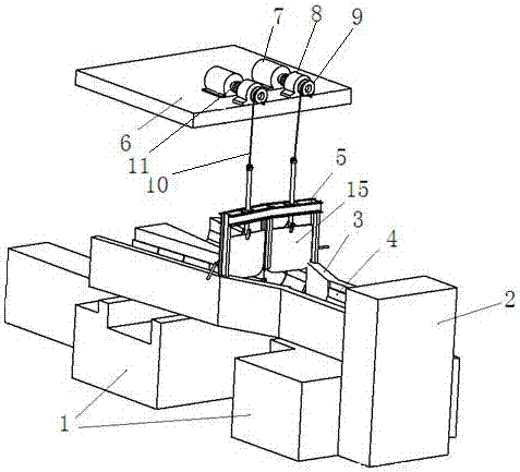
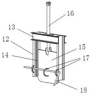
[0018] The invention consists of a foundation platform 1, a slag separating pipeline 3, a liner plate 4, a gate 5, a lifting platform 6 and a lifting mechanism.

[0019] figure 1 It shows that the foundation platform 1 for pouring concrete is located between the slag ditch 2 and the two filter tanks, and the slag separating pipeline 3 is located on the foundation platform 1 . The level of the foundation platform 1 on the side of the slag ditch 2 is higher than the level on the side of the two filter tanks, and the level of the bottom surface of the slag separating pipeline 3 on the side of the slag ditch 2 is higher than that on the side of the two filter tanks . The pouring height of the foundation platform 1 and the slag separating pipeline 3 is inclined from the slag ditch 2 to the direction of the two filter tanks, and a certain slope is maintained to facilitate the automatic flow of the slag slurry from the slag ditch 2 to the filter tanks.

[0020] figure 1 It shows t...


PUM


Abstract

The invention discloses a blast furnace slag slurry conveying conversion device not liable to be damaged and belongs to the technical field of blast furnace iron smelting equipment. The blast furnace slag slurry conveying conversion device is used for conveying blast furnace slag slurry to different filter pools. According to the technical scheme, a concrete-poured foundation platform is located between a slag ditch and the two filter pools. A slag dividing pipeline is located on the foundation platform. A main pipeline is arranged at one end of the slag diving pipeline, and a slag inlet of the main pipeline is connected with the slag ditch. Two branch pipelines are arranged at the other end of the slag diving pipeline. Slag outlets of the two branch pipelines are connected with slag inlets of the two filter pools correspondingly. Gates are mounted at slag inlets of the two branch pipelines correspondingly. A lifting platform is arranged above the gates. Two lifting mechanisms are mounted on the lifting platform and connected with the upper ends of the two gates correspondingly. The structure is simple, mounting is convenient, the using effect is good, the manufacturing cost is low, the spare part cost is saved, the overhaul cost is reduced, the whole device operates stably, normal operation of a blast furnace is guaranteed, and significant economic benefits are achieved.

Description

technical field [0001] The invention relates to a conversion device used for conveying blast furnace slag to different filter pools, and belongs to the technical field of blast furnace ironmaking equipment. Background technique [0002] The blast furnace slag conversion device is responsible for the transportation and diversion of water slag, realizing the recycling of water used in the water slag area and the recycling and reuse of used slag. The slag-slurry conversion device is located between the slag ditch and the two filter pools. Its function is to guide the water slag discharged from the slag ditch to the filter pool when the blast furnace is tapping. The distributing device for slurry conversion introduces water slag into another filter tank and continues to output water slag until the iron tapping is completed. Then the water slag is separated from water in the filter tank, the slag is recycled and reused, and the water is recycled. The currently used slurry conver...

Claims


Application Information

Patent Timeline
Patent Type & Authority Applications(China)
IPC IPC(8): C21B3/06C21B3/08F16K3/02F16K3/312
CPCF16K3/0218F16K3/312C21B3/06C21B3/08Y02W30/50
Inventor 车明浩张旭敏马明鑫田霄龙蔡福明江立中代爽赵国英何友国
Owner TANGSHAN IRON & STEEL GROUP
Why Eureka
Try Eureka