Control method for engineering machinery hydraulic system

A technology of hydraulic system and control method, which is applied in the directions of fluid pressure actuation system components, fluid pressure actuation system testing, mechanical equipment, etc. The effect of saving system power

Inactive Publication Date: 2019-05-28
HENAN INST OF ENG
View PDF6 Cites 0 Cited by
  • Summary
  • Abstract
  • Description
  • Claims
  • Application Information

AI Technical Summary

Problems solved by technology

[0006] In the above method, for the situation that the pressure is kept constant through the overflow of the relief valve, the power loss of the system is relatively large. When the pressure holding time is long or the relief valve needs to be operated frequently, it is generally seldom considered for power saving. application
For the situation where the pressure is kept constant through the pressure-holding circuit of the accumulator and the quantitative pump, although this method is widely used, it has a large impact on the system and may cause damage to the system
For the situation that the pressure is kept constant through the pressure cut-off valve, the pressure compensation mechanism of the pressure cut-off valve must be additionally added to the constant pressure pump, thus increasing the cost of the hydraulic system

Method used


Image

  • Control method for engineering machinery hydraulic system

Examples


Embodiment 1

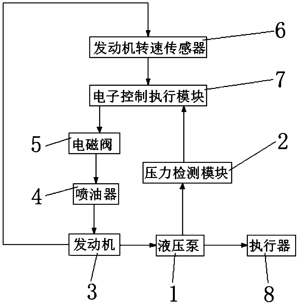
[0034] The present invention provides a control method for construction machinery hydraulic system, specifically as figure 1 As shown, the hydraulic system includes:

[0035] The hydraulic pump 1 is used to provide hydraulic oil for the hydraulic pipeline;

[0036] The pressure detection module 2 is used to detect the outlet pressure of the hydraulic pump 1. The pressure detection module 2 in this embodiment is a pressure sensor and is installed at the oil discharge port of the hydraulic pump 1;

[0037] The engine 3 is used to provide power for the hydraulic pump 1;

[0038] The fuel injector 4 is used to provide fuel for the engine 3;

[0039] The solenoid valve 5 is used to control the fuel injection quantity of the fuel injector 4;

[0040] The engine speed sensor 6 is used to detect the speed of the engine 3;

[0041] The electronic control execution module 7 is used to control the opening of the solenoid valve 5 according to the outlet pressure of the hydraulic pump ...


PUM


Abstract

The invention provides a control method for a hydraulic system of an engineering machine, and belongs to the technical field of hydraulic pressure and control. The control method comprises the following steps: an electronic control execution module judges a working mode of an executor according to a system input signal; a pressure detection module detects exit pressure of a hydraulic pump, and an engine speed sensor detects a speed of an engine; and the electronic control execution module compares the exit pressure with preset pressure according to the judged working mode and compares the speed of the engine and the engine speed in such mode, and under the condition that the exit pressure does not meet preset pressure, the electronic control execution module controls the opening of an electromagnetic valve to change the oil spraying quantity of an oil sprayer, then the speed of the engine is changed and thus power transmitted to the hydraulic pump by the engine is changed. According to the control method, by controlling the displacement of the hydraulic pump, the exit pressure of the hydraulic system can quickly and efficiently reach the preset pressure of the hydraulic system, so that the system power is saved, and the working stability, the accuracy, the flexibility and the working efficiency of the hydraulic system are improved.

Description

technical field [0001] The invention belongs to the technical field of hydraulic pressure and control, and in particular relates to a control method for hydraulic systems of engineering machinery. Background technique [0002] In many machines, it is necessary to keep the system pressure at a constant pressure, such as the distribution hydraulic system of the excavator bucket during the lifting process, the bulldozer blade during the bulldozing process, etc. Therefore, the hydraulic drive has a very important role in various machines. Wide range of applications. At present, there are usually the following methods to keep the system pressure of the hydraulic system constant: [0003] 1) Keep the system pressure constant through the overflow valve; [0004] 2) Keep the system pressure constant through the accumulator and quantitative pump; [0005] 3) Keep the system pressure constant through the pressure cut-off valve on the constant pressure pump. [0006] In the above m...

Claims


Application Information

Patent Timeline
Patent Type & Authority Patents(China)
IPC IPC(8): F15B21/08F15B21/00F15B19/00
CPCF15B19/00F15B21/001F15B21/087
Inventor 邓书显葛鑫鑫李会序王万永杨瑞
Owner HENAN INST OF ENG
Why Eureka
Try Eureka