Gas turbine electricity/steam cogeneration system employing smoke exhaust waste heat to increase yield of seam

A technology of gas turbine and waste heat steam, which is applied in the steam generation method using heat carrier, gas turbine device, steam generation, etc., which can solve the problems of wasting water resources, large amount of smoke exhaust, and waste, so as to improve the utilization rate of heat energy and reduce operation Cost, the effect of reducing project cost

Inactive Publication Date: 2017-09-22
刘绍允
View PDF6 Cites 3 Cited by
  • Summary
  • Abstract
  • Description
  • Claims
  • Application Information

AI Technical Summary

Problems solved by technology

[0002] At present, gas turbine electric / steam cogeneration systems that use natural gas as fuel exhaust a large amount of smoke. Recovering the latent and sensible heat in the exhaust smoke is an important energy-saving measure, but the existing technology only uses this part of the heat to generate heat. Water, but the consumption of a large amount of hot water is a problem. If it is not solved properly, it will not only save energy, but also waste water resources, and the cost of the project will remain high.
In addition, in the prior art, the thermal energy utilization rate of the downstream steam heating system is also low, and there is a loss of mass and heat in the heat exchange of the working fluid, resulting in waste of energy and waste of water resources

Method used


Image

  • Gas turbine electricity/steam cogeneration system employing smoke exhaust waste heat to increase yield of seam
  • Gas turbine electricity/steam cogeneration system employing smoke exhaust waste heat to increase yield of seam
  • Gas turbine electricity/steam cogeneration system employing smoke exhaust waste heat to increase yield of seam

Examples


Embodiment Construction

[0016] The content of the present invention will be further described below in conjunction with the accompanying drawings, but the actual application form of the present invention is not limited to the illustrated embodiment.

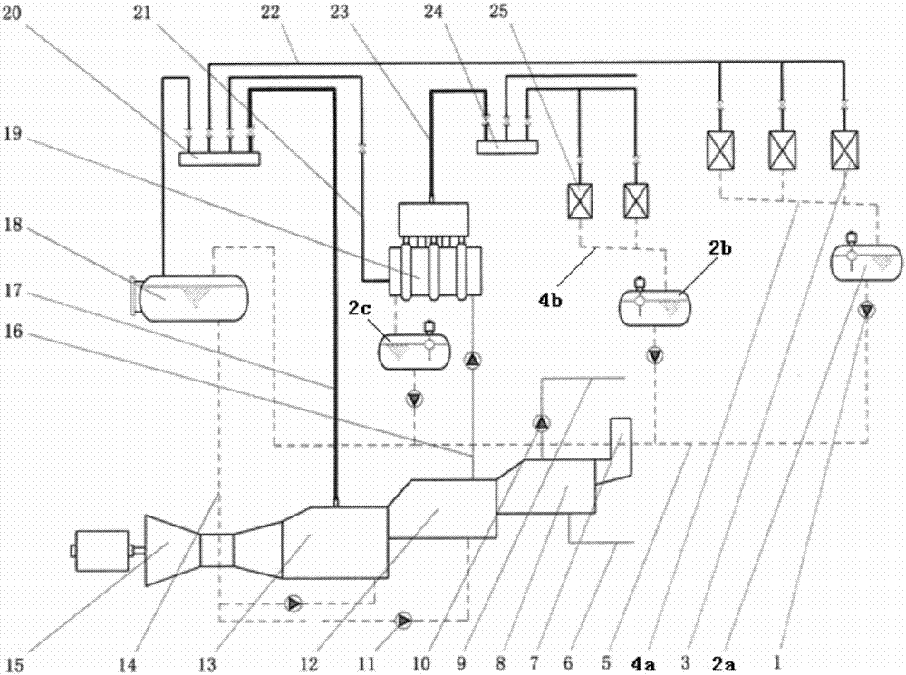
[0017] See attached figure 1 , the gas turbine electrical / steam cogeneration system for increasing steam production by using exhaust waste heat according to the present invention includes a gas turbine generating set 15, a waste heat steam boiler 13, a high-temperature hot water boiler 12, a secondary hot water boiler 8, a chimney 7, and a cylinder 19 , heat equipment 3, steam pipe 20, secondary steam boiler 19, low pressure sub-cylinder 24, low pressure heat equipment 25, first liquid collection tank 2a, second liquid collection tank 2b, third liquid collection tank 2c, liquid collection Tank 18, hot water pump, high temperature pump and other equipment, steam main pipe 17, steam heating pipe 21, steam pipe 22, low pressure steam main pipe 23, condensa...


PUM


Abstract

The invention relates to a gas turbine electricity/steam cogeneration system which employs smoke exhaust waste heat to increase the yield of steam. The gas turbine electricity/steam cogeneration system consists of a gas turbine generating set, a waste heat steam boiler, a high-temperature water boiler, a secondary hot water boiler, a steam header, a secondary steam boiler, a low-pressure steam header, a first liquid collection box, a second liquid collection box, a liquid gathering box and the like. A smoke outlet of a gas turbine is connected with the waste heat steam boiler; a smoke port of the waste heat steam boiler is connected with the high-temperature water boiler; the high-temperature water boiler is connected with the secondary hot water boiler, and is in space connection with water of the secondary steam boiler through a hot water pipe; the secondary steam boiler is connected with the steam header through a steam additional heating pipe; a steam pipe of the waste heat steam boiler is connected with the steam header; steam pipes of heat using equipment are connected with the steam header; and condenser pipes of the heat using equipment are connected with the first liquid collection box and the second liquid collection box respectively; the waste heat steam boiler is equipped with a third liquid collection box, and condenser water is sent into the liquid gathering box through a high-temperature pump; and a condenser water main pipe at the bottom of the liquid gathering box conveys the condenser water to the waste heat steam boiler and the high-temperature water boiler.

Description

technical field [0001] The invention belongs to the technical field of thermal energy engineering systems, and relates to a gas turbine-electric / steam cogeneration system for increasing steam production by using exhaust waste heat. Background technique [0002] At present, gas turbine electric / steam cogeneration systems that use natural gas as fuel exhaust a large amount of smoke. Recovering the latent and sensible heat in the exhaust smoke is an important energy-saving measure, but the existing technology only uses this part of the heat to generate heat. Water, but the consumption of a large amount of hot water is a problem. If it is not solved properly, it will not only save energy, but also waste water resources, and the project cost will remain high. In addition, in the prior art, the thermal energy utilization rate of the downstream steam heating system is also low, and there is a loss of mass and heat of the working fluid in the heat exchange, resulting in waste of ene...

Claims


Application Information

Patent Timeline
Patent Type & Authority Applications(China)
IPC IPC(8): F22B1/18F22D11/06F23J15/06F24H1/00F02C6/00
CPCF02C6/00F22B1/1815F22D11/06F23J15/06F24H1/00Y02E20/14Y02E20/30
Inventor 刘绍允
Owner 刘绍允
Why Eureka
Try Eureka