Extra-large drying oven structure provided with carbon fiber barrel

A carbon fiber and oven technology, used in drying, dryers, drying solid materials, etc., can solve the problems of unsafe transportation, heat loss, uneven heating, etc., to improve safety performance, reduce negative effects, and prevent heat loss. Effect

Inactive Publication Date: 2017-09-22
JIANGSU GUANGSHENGYUAN TECH DEV
View PDF0 Cites 7 Cited by
  • Summary
  • Abstract
  • Description
  • Claims
  • Application Information

AI Technical Summary

Problems solved by technology

At present, gluing and drying are required in the production process of carbon fiber cylinders, and the length of carbon fiber cylinders is between 14 and 15 meters, and the diameter is about 5 meters. The following disadvantages: 1. The carbon fiber cylinder drying equipment currently used is directly heated by the electric heating tube, the heating is uneven, the temperature difference between various parts inside the drying equipment is large, and the drying effect is poor; 2. The drying equipment The temperature cannot be uniformly cooled at the same interval time, the temperature control cannot meet the requirements, and the cooling effect is poor; 3. The observation windows on the existing drying equipment are all single-layer tempered glass wrapped by inner and outer fixing rings, which have poor sealing performance and are easy to Lead to heat loss; 4. Once people are locked in the existing carbon fiber cylinder drying equipment, it is difficult to escape, and the safety performance is poor; 5. The existing drying equipment is directly driven by a geared motor to rotate the carbon fiber cylinder for drying. Only relying on the geared motor to drive is likely to cause vibrations during the rotation of the carbon fiber cylinder, and even distort and deform the m

Method used


Image

  • Extra-large drying oven structure provided with carbon fiber barrel
  • Extra-large drying oven structure provided with carbon fiber barrel
  • Extra-large drying oven structure provided with carbon fiber barrel

Examples


Example Embodiment

[0025] The specific content of the present invention will be described in detail below with reference to the drawings and specific embodiments.

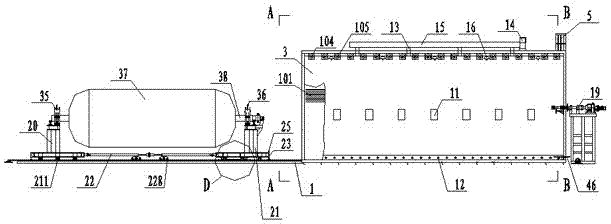
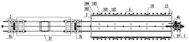
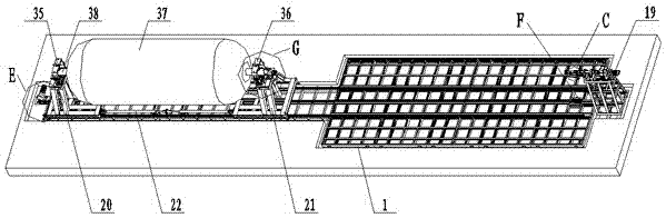
[0026] Such as figure 1 , figure 2 , image 3 , Figure 4 , Figure 5 , Image 6 , Figure 7 , Figure 8 , Picture 9 , Picture 10 , Picture 11 , Picture 12 , Figure 13 , Figure 14 , Figure 15 As shown, the carbon fiber cylinder super large oven structure includes: a frame 1 and a slide rail 2 arranged in the frame 1, an oven 3 is provided at the upper end of the frame 1, and a drying cavity is provided in the oven 3 4. An escalator 5 is provided on the oven 3, and hot air circulating side air ducts 6 are symmetrically arranged on both sides of the inside of the oven 3, and the upper ends of the two hot air circulating side air ducts 6 are set on the upper end of the oven 3 The hot air circulating upper air ducts 7 are connected to each other, and the hot air circulating air outlet 8 communicating with the drying cavity 4 is prov...


PUM


Abstract

The invention discloses an extra-large drying oven structure provided with a carbon fiber barrel. The structure comprises a rack and sliding rails arranged in the rack. A drying oven is arranged at the upper end of the rack. A drying cavity is formed in the drying oven. A ladder is arranged on the drying oven. Heated air circulation side air ducts are symmetrically formed in the two sides of the interior of the drying oven. The upper ends of the two heated air circulation side air ducts communicate with each other through a heated air circulation upper air duct formed in the upper end of the drying oven. The lower ends of the heated air circulation side air ducts are provided with heated air circulation air outlets communicating with the drying cavity. A heated air circulation air return port communicating with the drying cavity is formed in the middle of the heated air circulation upper air duct. A plurality of heating units are uniformly arranged in the positions, at the upper ends of the heated air circulation side air ducts, of the drying oven correspondingly.

Description

technical field [0001] The invention relates to a drying device, in particular to a super large oven structure of a carbon fiber cylinder. Background technique [0002] Carbon fiber tubes are widely used in the aerospace field. Carbon fiber is a material that is stronger than steel and lighter than aluminum. It has many advantages in mechanics, electricity and heat. It also has excellent electrical conductivity and anti-magnetization. , high temperature resistance and chemical corrosion resistance, it is considered to be an advanced material with the best comprehensive performance. At present, gluing and drying are required in the production process of carbon fiber cylinders, and the length of carbon fiber cylinders is between 14 and 15 meters, and the diameter is about 5 meters. The following disadvantages: 1. The carbon fiber cylinder drying equipment currently used is directly heated by the electric heating tube, the heating is uneven, the temperature difference between ...

Claims


Application Information

Patent Timeline
IPC IPC(8): F26B13/10F26B13/14F26B21/04F26B23/04F26B25/00F26B25/02F26B25/08F26B25/12
CPCF26B13/108F26B13/14F26B21/04F26B23/04F26B25/003F26B25/02F26B25/08F26B25/12
Inventor 金传广徐晓洪刘兆诚
Owner JIANGSU GUANGSHENGYUAN TECH DEV
Why Eureka
Try Eureka