
Portable high-temperature and high-pressure mechanical test device

A high-temperature, high-pressure, mechanical test technology, applied in the direction of applying stable tension/pressure to test the strength of materials, etc., can solve the problems of limiting the use range of stretching machines, limiting the ultimate pressure of containers, increasing equipment investment costs, etc., and achieving temperature resistance Good pressing effect, less material consumption and low cost

Active Publication Date: 2017-09-22
ZHEJIANG UNIV OF TECH
View PDF4 Cites 4 Cited by
  • Summary
  • Abstract
  • Description
  • Claims
  • Application Information

AI Technical Summary

Problems solved by technology

This greatly increases the input cost of the equipment, and because of this pressure limitation, the ultimate pressure of the experimental container is limited (the internal pressure of too high pressure may directly break the sample)
In addition, it also limits the scope of use of the stretching machine itself as a traditional experimental equipment.

Method used


Image

  • Portable high-temperature and high-pressure mechanical test device
  • Portable high-temperature and high-pressure mechanical test device
  • Portable high-temperature and high-pressure mechanical test device

Examples


Embodiment Construction

[0036] The present invention will be further described below in conjunction with the accompanying drawings and specific embodiments.

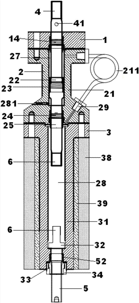
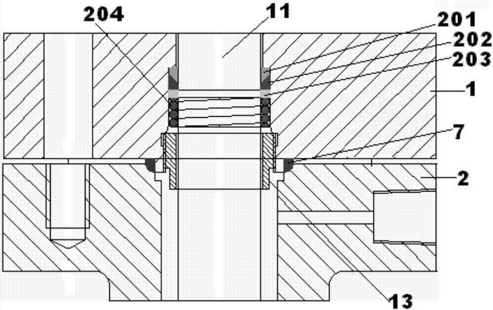
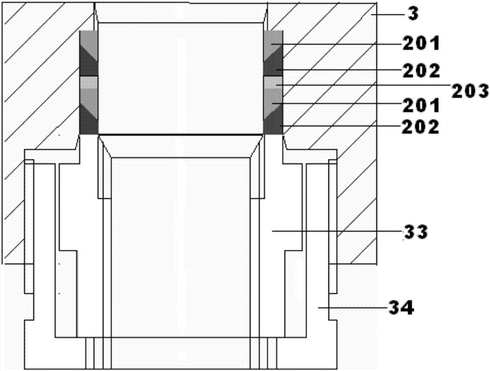
[0037] Such as figure 1 A portable high-temperature and high-pressure mechanical test device shown includes a cover 1, an upper kettle body 2 connected to the cover, a lower kettle body 3 connected to the upper kettle body, an upper stretch rod 4 and a lower stretch rod 5; The upper end of the upper stretching rod is connected with the stretching machine, the upper stretching rod extends into the cover, the upper kettle body and the lower kettle body, the upper part of the lower stretching rod extends into the lower kettle body, and the relative distance between the upper stretching rod and the lower stretching rod Each end is provided with chucks 6; the upper kettle body includes an upper cavity 21 with a first vertical through hole, which is sequentially arranged between the middle part of the upper stretch rod and the first vertical through ...


PUM


Abstract

The invention discloses a portable high-temperature and high-pressure mechanical test device. The portable high-temperature and high-pressure mechanical test device comprises a cover, an upper kettle body connected with the cover, a lower kettle body connected with the upper kettle body, an upper tension bar and a lower tension bar. The upper end of the upper tension bar is connected with a tension machine, the upper tension bar stretches into the cover, the upper kettle body and the lower kettle body, the upper portion of the lower tension bar stretches into the lower kettle body, and the opposite ends of the upper tension bar and the lower tension bar are provided with chucks. The upper kettle body comprises an upper cavity, an upper annular support piece, a first dynamic seal structure, a second dynamic seal structure and a lower annular support piece, wherein the upper cavity is provided with a first vertical through hole, the upper annular support piece and the first dynamic seal structure are arranged between the middle of the upper tension bar and the first vertical through hole in sequence from top to bottom, and the second dynamic seal structure and the lower annular support piece are arranged between the upper tension bar and the lower portion of the first vertical through hole in sequence from top to bottom. The portable high-temperature and high-pressure mechanical test device has the advantages of being convenient to disassemble and assemble, good in temperature-resistant and pressure-resistant effect and high in safety.

Description

technical field [0001] The invention relates to the technical field of high-pressure hydrogen experimental equipment, in particular to a portable high-temperature and high-pressure dynamic testing device that can be used in conjunction with a common stretching machine. Background technique [0002] Hydrogen energy, petrochemical industry, nuclear power and ocean development are important components of my country's energy strategy. In these fields, equipment often needs to operate in high temperature, high pressure and high corrosion environment. [0003] The corrosion problem of high temperature and high pressure is an important factor that threatens the safe and stable operation of equipment. Once the equipment operating in the high temperature and high pressure environment fails, it may cause very serious consequences. For example: in 2003, a H-containing gas occurred in a gas field in eastern Sichuan, Sichuan 2 The oil and gas leakage accident caused more than 200 deat...

Claims


Application Information

Patent Timeline
Patent Type & Authority Applications(China)
IPC IPC(8): G01N3/18
Inventor 周成双王雪函吴恒毅张盛盛胡诗音嵇伟明张林
Owner ZHEJIANG UNIV OF TECH
Learn More