
Infrared gas sensing system

A gas sensing and infrared technology, which is applied in measuring devices, material analysis through optical means, instruments, etc., can solve the problems that the temperature of the detector module cannot be kept consistent, reduce environmental impact factors, and have large differences in heat loss, etc., to achieve Improve anti-interference, wide detection range, and reduce the effect of influence

Inactive Publication Date: 2017-09-22
PROMISENSE ELECTRONICS TECH CO LTD
View PDF9 Cites 2 Cited by
  • Summary
  • Abstract
  • Description
  • Claims
  • Application Information

AI Technical Summary

Problems solved by technology

However, the actual situation is that this kind of straight tube dual optical path will cause the temperature of the two detector modules to be inconsistent due to the long optical path and the short optical path. When the temperature at the light source end changes, the heat will be transferred to the detector module at the end of the long optical path. The time required to reach the detector module at the end of the short optical path is inconsistent, and the difference in heat loss is also large, resulting in nonlinear temperature drift, which makes this structure useless
[0005] On the other hand, when the NDIR gas sensor measures a gas with a small absorption coefficient such as CH4, and the resolution needs to be below 50PPM, a long absorption path L is required in the structure. The same end of the tracheal chamber, and a mirror placed at the other end of the straight pipe air chamber, so that the optical path is increased to about twice the original, but the heating of the light source of this structure causes serious temperature drift in the measurement results of the detector, and due to The signal optical path and the reference optical path have the same optical path, and the above-mentioned dual optical path technology cannot be used to reduce environmental impact factors

Method used


Image

  • Infrared gas sensing system
  • Infrared gas sensing system
  • Infrared gas sensing system

Examples


Embodiment Construction

[0029] The present invention will be described in detail below in conjunction with various embodiments shown in the drawings.

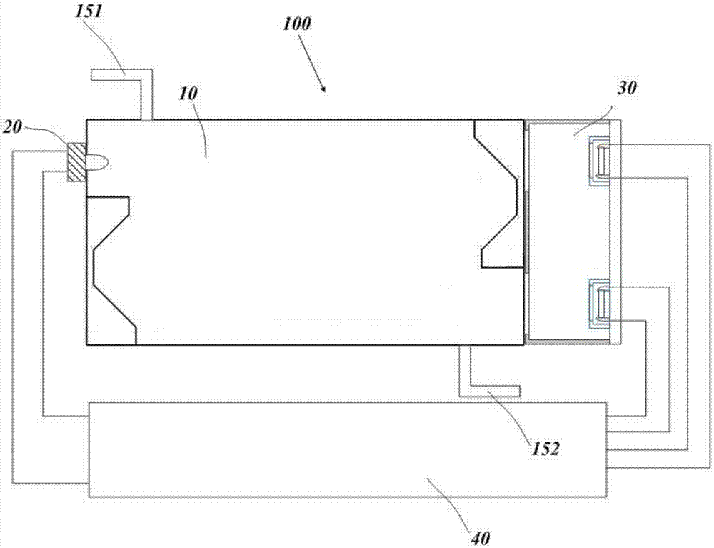
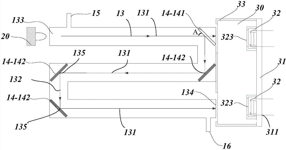
[0030] See Figure 1 to Figure 6 As shown, the present invention relates to an infrared gas sensing system 100 comprising a base 10 having a broken line channel 13, an infrared light source 20 disposed adjacent to the base 10, and a detection module disposed adjacent to the base 10 30, and a control module 40 electrically connected to the infrared light source 20 and the detection module 30.

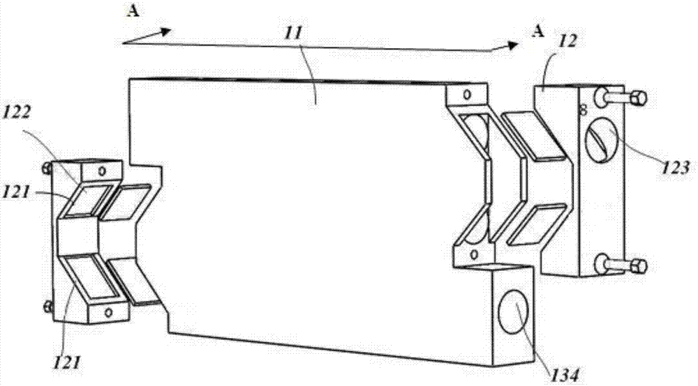
[0031] The base 10 includes a substrate 11, at least two mounts 12 matched with the substrate 11, a mirror 14 arranged between the substrate 11 and the mounts 12, and a mirror 14 arranged on the substrate 11. The air inlet 15 and the air outlet 16 on the top, in this embodiment, the number of the mounting base 12 is two, and they are respectively located on both sides of the base plate 11 .

[0032] The two side walls of the base plate 11 are provided with two p...


PUM


Abstract

The invention provides an infrared gas sensing system. The infrared gas sensing system comprises an infrared light source, a base and a probing module, the base is provided with a zigzag channel arranged inside and a reflecting mirror arranged in the zigzag channel, the zigzag channel is provided with several channel corners, and the reflecting mirror comprises a half-transmitting-half-reflecting mirror arranged at one of the channel corners and a full-reflecting mirror arranged at other channel corners; the probing module comprises a heat conducting baseboard and two probe modules which are arranged at the same side of the heat conducting baseboard and have the same specification. Through the structure, the influence caused by light intensities which are measured by the two probe module represents the linear relation due to external environment changes, and is conveniently eliminated through computation, therefore the anti-jamming performance of the system to the external environment changes is improved; by conducting thermal optimization on the two probe sensor modules, the temperatures of the two probe modules are identical, and the influence of the temperature on the measurement result of the probe modules is reduced.

Description

technical field [0001] The invention relates to the design of a non-dispersive infrared gas sensing system (NDIR) with a long-distance composite optical path, belonging to the field of infrared gas detection. Background technique [0002] Non-dispersive infrared gas sensing (NDIR) technology is a gas sensing technology with high precision, good stability and long life. The light intensity contrast calculates the concentration of the gas, and Beer-Lambert's law: I=I 0 • exp(-μCL). Among them, I is the infrared light intensity reaching the detector when there is gas absorption, and I 0 is the light intensity when there is no gas absorption, C is the gas concentration in the chamber, L is the length of the chamber or the path length of infrared light, and μ is the absorption coefficient of the gas. [0003] The traditional NDIR system adopts a single optical path structure, that is, the infrared light passes through the optical path to reach the signal detector and the refer...

Claims


Application Information

Patent Timeline
IPC IPC(8): G01N21/17G01N21/01
CPCG01N21/01G01N21/17G01N2021/0112
Inventor 郭安波俞骁
Owner PROMISENSE ELECTRONICS TECH CO LTD
Learn More