Method for improving steady-state operating range of electric power spring

A steady-state operating range, power spring technology, applied in power network operating system integration, AC network voltage adjustment, climate sustainability, etc. performance, reduced complexity, and the effect of extending the operating range

Active Publication Date: 2017-09-22
SHANGHAI JIAO TONG UNIV +3
View PDF4 Cites 6 Cited by
  • Summary
  • Abstract
  • Description
  • Claims
  • Application Information

AI Technical Summary

Problems solved by technology

[0005] However, like mechanical springs, electric springs also operate in a limited range, which is limited by factors such as DC link voltage, critical load and non-critical load operating voltage range, network element parameters, etc.
When the grid-side voltage fluctuates too much, the electric spring will not be able to complete the control target and fail

Method used


Image

  • Method for improving steady-state operating range of electric power spring
  • Method for improving steady-state operating range of electric power spring
  • Method for improving steady-state operating range of electric power spring

Examples


Embodiment Construction

[0046] For ease of understanding, the present invention will be described below in conjunction with the accompanying drawings, but this should not limit the protection scope of the present invention.

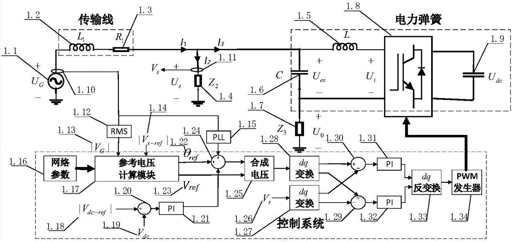
[0047] figure 1 It is the circuit and control topology diagram of the electric spring system in the prior art. As shown in the figure, the circuit composed of the voltage source inverter and the LC filter in the dotted line box on the right is the electric spring, and the electric spring and the non-critical load are connected in series. Constitute an intelligent load, and then run in parallel with the key load to connect to the power grid; the lower dotted line box is the electric spring control block diagram. where U G is the grid side voltage, R 1 , L 1 is the transmission line impedance, Z 2 is the critical load, Z 3 for non-critical loads. Generally, voltage-sensitive loads are regarded as critical loads, and the voltage of critical loads is stabilized by electric spr...


PUM


Abstract

The invention discloses a method for improving a steady-state operating range of an electric power spring. The method comprises the steps of calculating a steady-state grid-side voltage representation vector according to an electric power system network topology and electrical parameters corresponding to the electric power spring, and drawing a vector track curve; obtaining a steady-state operating track and range of the electric power system through analysis by a geometric method according to the steady-state grid-side voltage vector track; obtaining a system optimal control track under the grid-side voltage out-of-limit condition according to the steady-state grid-side voltage vector track by combination with the geometric method; and obtaining an optimization calculation method for the expanded steady-state operating range of the electric power spring and the key load voltage set values of the electric power system in the grid-side voltage non-out-of-limit condition and the grid-side voltage out-of-limit condition. By adoption of the method, the problem of failure of the electric power spring in the grid-side voltage out-of-limit condition can be effectively avoided, so that the steady-state operating range of the electric power spring is expanded, and the safety and stability operation performance of the electric power spring system are obviously improved.

Description

technical field [0001] The invention belongs to the technical field of smart grid control and relates to a method for improving the steady-state operating range of an electric spring. Background technique [0002] With the large-scale grid connection of renewable energy such as wind energy and solar energy, the intermittent, unstable, and low prediction accuracy of renewable energy power generation has caused the imbalance between power generation and load demand to become increasingly prominent, affecting the power system. Operational safety and power quality of power supply. [0003] Solving a series of problems caused by renewable energy grid integration through demand-side management has been widely recognized in the industry. However, ordinary demand-side technologies generally require end-user participation, or at the expense of user experience, and energy storage-based technologies face high costs. . In response to the above situation, the University of Hong Kong pr...

Claims


Application Information

Patent Timeline
Patent Type & Authority Applications(China)
IPC IPC(8): H02J3/24H02J3/14
CPCH02J3/14H02J3/24Y02B70/3225Y04S20/222
Inventor 程益生李国杰汪可友冯琳韩蓓
Owner SHANGHAI JIAO TONG UNIV
Why Eureka
Try Eureka