Laser cleaning device

A laser cleaning and cleaning technology, applied in the field of laser applications, can solve the problems of low cleaning efficiency, limited cleaning efficiency, low laser power, etc., and achieve high cleaning efficiency, fast and efficient cleaning effect

Active Publication Date: 2017-09-26
武汉翔明激光科技有限公司
View PDF8 Cites 24 Cited by
  • Summary
  • Abstract
  • Description
  • Claims
  • Application Information

AI Technical Summary

Problems solved by technology

[0006] At present, the laser power used in the existing laser cleaning system for metal surface dirt is small, and the cleaning efficiency is limited
Since the beam adjustment system adopted scans the beam on the surface of the workpiece through the two-dimensional galvanometer system, and the reciprocating swing angle range of the galvanometer is limited, when the width of the workpiece to be cleaned is large, it is necessary to increase the distance between the workpiece surface and the beam adjustment system. The distance between them will cause the laser spot area irradiated on the surface of the workpiece to be too large and make its energy density too low, which cannot guarantee the cleaning quality and cleaning

Method used


Image

  • Laser cleaning device
  • Laser cleaning device
  • Laser cleaning device

Examples


Embodiment 1

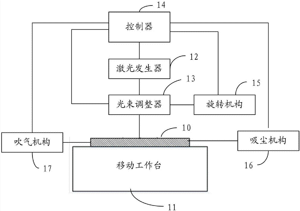
[0046] Such as figure 1 As shown, the laser cleaning device for cleaning the object 10 to be cleaned includes: a mobile workbench 11, a laser generator 12, a beam adjuster 13, a controller 14, a rotating mechanism 15, a dust suction mechanism 16 and an air blowing mechanism 17, wherein ,

[0047] The mobile workbench 11 is used to place the parts to be cleaned 10, and when the mobile workbench 11 moves, the parts to be cleaned 10 are driven to move horizontally;

[0048] The laser generator 12 is arranged corresponding to the mobile workbench 11 for emitting laser light;

[0049] The beam adjuster 13 is arranged corresponding to the laser generator 12, and is used to adjust the laser beam into a strip shape and scan the scanning laser beam of the object to be cleaned 10 at a set scanning speed;

[0050] The controller 14 is connected with the mobile worktable 11, the laser generator 12 and the beam adjuster 13 respectively, and is used to set the laser power of the laser gen...

Embodiment 2

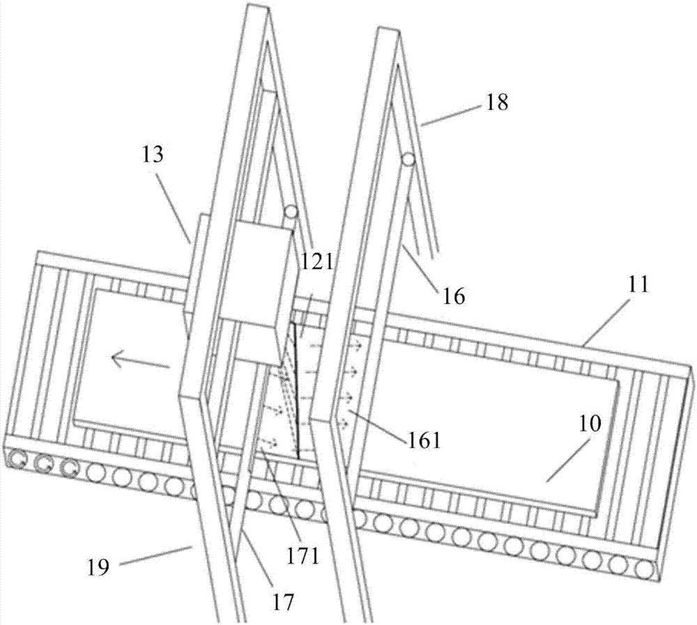
[0071] Such as image 3 and Figure 4 As shown, the laser cleaning device includes: a controller 14 , a laser generator 12 , a beam adjuster 13 , an air blowing mechanism 17 , a dust suction mechanism 16 , and a moving work 11 and a rotating mechanism 15 . The controller 14 can control the laser generator 12 and the beam adjuster 13, so that the laser generator 12 emits a laser beam 121 with set process parameters, and transmits the laser beam 121 to the beam adjuster 13 through an optical fiber for beam shaping. At the same time, the controller 14 can also control the movement of the movable worktable 11, cooperate with the auxiliary function of the air blowing mechanism 17 and the dust suction mechanism 16 to clean the surface of the workpiece 10 to be cleaned evenly and efficiently, thereby removing the oxide film on the surface of the workpiece. In this embodiment, the mobile workbench 11 is a roller workbench; the controller 14 includes an input and output device 141 , a...


PUM

PropertyMeasurementUnit
Lengthaaaaaaaaaa
Widthaaaaaaaaaa

Abstract

The invention discloses a laser cleaning device. The laser cleaning device comprises a movable workbench, a laser generator, a beam regulator, a controller and a rotating mechanism, wherein the movable workbench is used for holding to-be-cleaned parts; the laser generator corresponds to the movable workbench and is used for emitting laser; the beam regulator corresponds to the laser generator and is used for regulating the laser into a long strip shape and scanning the laser for scanning the to-be-cleaned parts at a set scanning speed; the controller is connected with the movable workbench, the laser generator and the beam regulator, and used for setting the laser power of the laser generator, the moving speed of the movable workbench and the setting scanning speed of the beam regulator and determining the compensation angular speed according to the moving speed and the scanning speed; and the rotating mechanism is connected with the beam regulator and the controller, and used for driving the beam regulator to rotate according to the compensation angular speed, so that the scanning track of the beam regulator is perpendicular to the moving direction of the to-be-cleaned parts. According to the cleaning device provided by the invention, plate workpieces with large widths can be efficiently cleaned.

Description

technical field [0001] The invention relates to the field of laser applications, in particular to a laser cleaning device. Background technique [0002] Hot rolling is relative to cold rolling, cold rolling is rolling below the recrystallization temperature, and hot rolling is rolling above the recrystallization temperature. During the hot rolling process, a layer of oxide film will be formed on the surface of the steel plate, which will affect the flatness and glossiness of the steel plate surface, reduce the surface quality of the steel plate, and cover up the surface defects of the strip steel, causing difficulties for the subsequent use of the steel plate. If these strips with oxide film are directly sent to the cold rolling mill for rolling, the surface quality and processing performance of the cold rolled plate will be affected, and even the damage of the circulation equipment and the cold rolling roll will be caused. Therefore, before the strip is cold-rolled, its ox...

Claims


Application Information

Patent Timeline
IPC IPC(8): B21B45/06B08B7/00
Inventor 王春明胡崇镜
Owner 武汉翔明激光科技有限公司
Why Eureka
Try Eureka