A multi-liquid cylinder type pit heat transfer tube extrusion molding device

A technology for extrusion molding and heat transfer tubes, which is used in molding tools, heat exchange equipment, metal processing equipment, etc., can solve the problem of no extrusion molding device for small-cell heat transfer tubes, etc., to improve the processing and manufacturing speed and manufacturing efficiency. , avoid the hydraulic system, improve the effect of processing and manufacturing speed

Inactive Publication Date: 2018-09-14
SOUTHWEST PETROLEUM UNIV
View PDF3 Cites 0 Cited by
  • Summary
  • Abstract
  • Description
  • Claims
  • Application Information

AI Technical Summary

Problems solved by technology

[0005] However, although there are various heat transfer tube processing and manufacturing devices, there is currently no extrusion molding device suitable for small cell heat transfer tubes.

Method used


Image

  • A multi-liquid cylinder type pit heat transfer tube extrusion molding device
  • A multi-liquid cylinder type pit heat transfer tube extrusion molding device
  • A multi-liquid cylinder type pit heat transfer tube extrusion molding device

Examples


Embodiment Construction

[0024] The present invention will be described in further detail below in conjunction with the accompanying drawings.

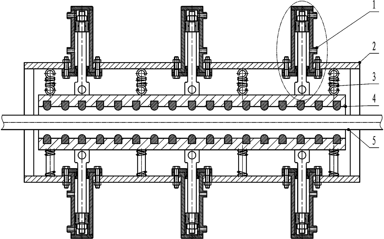
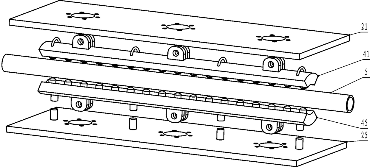
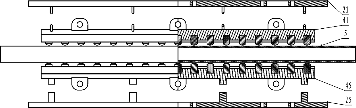
[0025] refer to Figure 1~Figure 4 , a hydraulic extrusion molding device for heat transfer tubes of dimples, which is composed of a hydraulic system 1, a support panel system 2, a spring system 3, and a pressure head system 4, and is used to extrude multiple dimples on the surface of a bare tube 5 at one time. cell. The hydraulic system 1 is bolted to the inner side of the support panel system 2 . The pin shaft on the lower side of the hydraulic system 1 is connected with the pressure head system 4 . A spring system 3 is installed between the pressure head system 4 and the hydraulic system 1 . The light pipe 5 is located at the center of the indenter system 4, and the light pipe 5 is axially installed with 2 to 8 rows of supporting panel systems. When working, multiple hydraulic cylinders provide driving force for the pressure head system 2, and the pres...


PUM


Abstract

The invention relates to a multi-hydraulic-cylinder type dimpled heat transfer pipe squeezing forming device. The device comprises hydraulic systems, a supporting system, spring systems, a pressing head system and a light pipe. The multi-hydraulic-cylinder type dimpled heat transfer pipe squeezing forming device is characterized in that the inner side of the supporting system is connected with the hydraulic systems through bolts; the lower sides of the hydraulic systems are connected with the pressing head system through pin shafts; each spring system is installed between the pressing head system and the corresponding hydraulic system; and the light pipe is located in the center of the pressing head system, and the light pipe is axially provided with two to eight columns of supporting panel systems. When the multi-hydraulic-cylinder type dimpled heat transfer pipe squeezing forming device works, multiple hydraulic cylinders provide drive force for the pressing head system, the pressing head system drives multiple punches to squeeze the light pipe simultaneously, the pressing head system is reset through a pull spring and a pressure spring, and finally a dimpled heat transfer pipe is formed. Compared with the prior art, multiple sets of pressing heads are adopted to squeeze the light pipe, and dimpled heat transfer pipes of different structural parameters are obtained by controlling structural parameters, such as the height, shape and number of the pressing heads; and in addition, machining and manufacturing efficiency of the dimpled pipes can also be improved, and the production cost is lowered.

Description

technical field [0001] The invention relates to the field of processing and forming of heat transfer tubes, in particular to a multi-liquid cylinder type pit heat transfer tube extrusion forming device. Background technique [0002] Heat transfer is a very common natural phenomenon and a common process in industries such as power, nuclear energy, electronics, transportation, refrigeration, chemical, petroleum, aerospace, etc. The heat exchanger occupies a key position in the above-mentioned industries. The heat exchanger is not only an indispensable part to ensure the normal operation of the entire engineering equipment, but also occupies an important share in the entire project in terms of metal consumption, power consumption and capital investment. . Taking a power plant as an example, if the boiler is also used as heat exchange equipment, the capital investment of the heat exchanger accounts for about 70% of the total investment of the power plant; in petrochemical indus...

Claims


Application Information

Patent Timeline
Patent Type & Authority Patents(China)
IPC IPC(8): B21D22/04B21D37/04B21D53/06
CPCB21D22/025B21D22/04B21D37/04B21D53/06
Inventor 梁政谢帅张梁王玉琳丁虎邓严
Owner SOUTHWEST PETROLEUM UNIV
Why Eureka
Try Eureka