Water pumping energy storage power generation device

A power generation device and pumped storage technology, which is applied in the directions of hydropower generation, energy saving and emission reduction, engine components, etc., can solve the problems of loss, unbalanced power consumption, unfavorable economic and safety of thermal power plants and nuclear power plants, etc.

Inactive Publication Date: 2017-09-26
刘运武
View PDF0 Cites 1 Cited by
  • Summary
  • Abstract
  • Description
  • Claims
  • Application Information

AI Technical Summary

Problems solved by technology

[0002] According to the existing technology, the electric energy generated by the power plant must be used as it is generated and cannot be stored, and the power consumption of users is very unbalanced in 24 hours a day. Frequent start-up and shutdown and load increase and decrease are not conducive to thermal power plants and nuclear power plants. The economy and safety of the plant unit, the solution is to start the pump to pump water when the power supply exceeds the demand on the grid, that is, the power consumption is low, that is, the electric energy is stored in the form of water energy, and the peak power to be used is the electric energy of the power plant. When the supply is in short supply, water is released to generate electricity. Regardless of the lift, that is, the water head, the water flow from the pipeline can only drive the water turbine to drive the generator after entering the factory building. According to the existing technology, 0.75 kilowatts of electric energy can be generated at most by pumping water with 1 kilowatt of electric energy, that is, Lost a quarter due to frictional resistance

Method used


Image

  • Water pumping energy storage power generation device
  • Water pumping energy storage power generation device
  • Water pumping energy storage power generation device

Examples


Embodiment Construction

[0017] Further clarification will be made below in conjunction with each accompanying drawing.

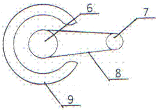
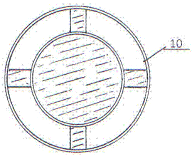
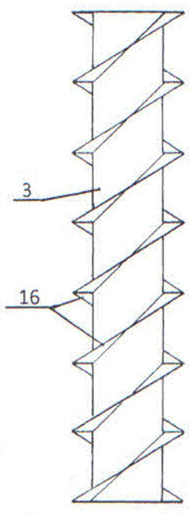
[0018] refer to Figure 1 to Figure 4 , in order to facilitate the installation of the bearing seat 5 containing bearings for the positioning of the water turbine at a certain length of the front end of the main shaft 4 of the water turbine, and to install the transmission wheel on the main shaft between the two bearing seats for power output, a single water turbine is used as a unit Divide the inner central part of the cross-section of the corresponding part of the pipe from the outer circumference at a small angle to form a gap for a certain length, so that the main shaft section without spiral pipes and blades protrudes out of the pipe, and set bearings and bearing seats on the exposed section. 5 and transmission wheel 6, the pipeline of section here is combined into the double-layer annular bobbin tube 9 with gap by inner and outer double-layer, and current passes between inner...


PUM


Abstract

The invention discloses a water pumping energy storage power generation device. The water pumping energy storage power generation device aims at improving drainage power generation efficiency and enabling the drainage power generation capacity to be equal to or larger than water pumping power consumption. According to the technical scheme, the water pumping energy storage power generation device is characterized in that a pipeline from top to bottom (or from bottom to top) is changed from one way to three or more back-and-forth ways, in other words, the pipeline is turned downwards, upwards and then downwards repeatedly, the pipeline is provided with an inlet and an outlet no matter how many times the pipeline is turned back and forth, and the pipeline is provided with one, two or more water turbines; and with one water turbine as the unit, the certain distance is reserved between one part of the internal center of the cross section of the corresponding portion of the pipeline and small-angle circumference of the periphery for enabling a main shaft provided with no spiral pipe or blade to stretch out of the pipeline, the upper and lower portions or front and back portions of the exposed section are each sleeved with a bearing and a bearing pedestal, the isolated portions, between the two bearing pedestals, of the main shaft are additionally provided with transmission wheels for outputting or inputting power, and therefore the longer the pipeline is and the larger the number of water turbines is, the larger the power generation capacity is.

Description

technical field [0001] The invention relates to a device for pumping water from a low place to a high place for temporary storage, and releasing it to flow downwards to drive a water turbine to drive a generator. Background technique [0002] According to the existing technology, the electric energy generated by the power plant must be used as it is generated and cannot be stored, and the power consumption of the user is very unbalanced in 24 hours a day. Frequent start-up and shutdown and load increase and decrease are not conducive to thermal power plants and nuclear power plants. The economy and safety of the plant unit, the solution is to start the pump to pump water when the power supply exceeds the demand on the grid, that is, the power consumption is low, that is, the electric energy is stored in the form of water energy, and the peak power to be used is the electric energy of the power plant. When the supply is in short supply, water is released to generate electrici...

Claims


Application Information

Patent Timeline
Patent Type & Authority Applications(China)
IPC IPC(8): F03B13/06
CPCF03B13/06F05B2220/706Y02E10/20Y02E60/16Y02P90/50
Inventor 刘运武
Owner 刘运武
Why Eureka
Try Eureka