Grain dryer

A grain dryer and drying technology, applied in dryers, grain drying, drying of solid materials, etc., can solve the problems of grain mildew, cumbersome labor intensity for farmers, and large floor space.

Inactive Publication Date: 2017-09-26
HEFEI KANGZHIHENG MACHINERY TECH CO LTD
View PDF2 Cites 7 Cited by
  • Summary
  • Abstract
  • Description
  • Claims
  • Application Information

AI Technical Summary

Problems solved by technology

[0002] After the farmers harvest the grain, if they do not dry the grain in time, the wet grain with moisture will rot, which will cause the economic loss of the farmers; and now, because the farmers cannot afford to buy and use th...

Method used


Image

  • Grain dryer
  • Grain dryer
  • Grain dryer

Examples


Embodiment 1

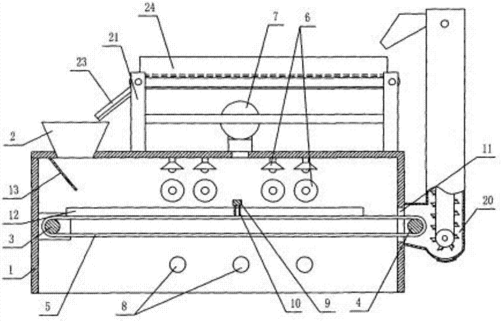
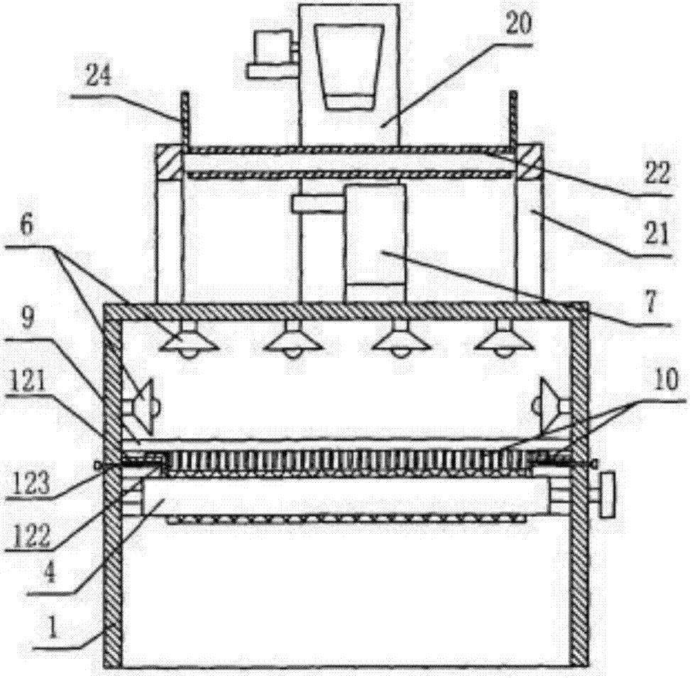
[0025] Such as figure 1 and figure 2 As shown, a grain dryer, which includes a drying machine box 1 and a feed funnel 2 is provided at the front of the top wall of the drying machine box 1. The front and rear of the drying machine box 1 are correspondingly installed with a drive roller 3 driven by a power mechanism and a slave The driving roller 4, the rear wall of the above-mentioned dryer box 1 is also provided with a discharge port 11 corresponding to the rear of the driven roller 4, and the two sides and the dryer box are covered between the driving roller 3 and the driven roller 4. 1. The conveyor mesh belt 5 attached to the inner surface of the side wall, and the outlet where the above-mentioned feeding funnel 2 extends into the dryer box 1 is located above the rear of the conveyor mesh belt 5;

[0026] A plurality of drying lamps 6 are respectively installed on the top wall and the side wall of the middle part of the drying cabinet 1, and the top wall of the drying ca...

Embodiment 2

[0029] combine again figure 1 and figure 2 Shown is a grain dryer, on the basis of the above structure, side baffles 12 are installed on the side wall of the drying machine box 1 to prevent grain from slipping down. The side baffle 12 includes a fixed plate 121 connected to the side wall of the dryer cabinet 1 and a vertical baffle 122 slidably connected to the fixed plate 121. The lower surface of the vertical baffle 122 is attached to the conveyor belt 5. Above, the above-mentioned vertical baffle plate 122 can be composed of a horizontal edge lapped on the fixed plate and a vertical edge extending to the conveying mesh belt 5, and the bottom of the vertical edge can be provided with an anti-slip and wear-resistant rubber strip;

[0030] In addition, on the side wall of the drying machine box 1, there is an adjusting bolt 123 whose inwardly extending end is rotatably connected to the vertical baffle 122 and drives the vertical baffle 122 to slide. The setting of the side b...

Embodiment 3

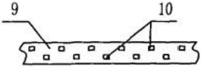
[0032] Such as figure 1 , figure 2 and image 3 As shown, a grain dryer, on the basis of the above structure, a grain turning mechanism is also installed in the drying box 1, wherein the grain turning mechanism includes a The supporting columns 9 are equipped with at least two rows of turning columns 10 before and after, and the turning columns 10 of the front and rear rows are arranged in a laterally staggered manner. In this embodiment, only one supporting column 9 is provided, and multiple drying irradiation The lamps 6 are divided into two groups before and after. The support column 9 is located in the middle of the two groups of drying irradiation lamps 6. The air inlet of the above-mentioned induced draft fan 7 is also located in the middle of the two groups of drying irradiation lamps. According to the requirements of the degree, a plurality of support columns 9 are arranged, and the plurality of support columns 9 are arranged at longitudinal intervals.

[0033] The...


PUM


Abstract

The invention discloses a grain dryer, and relates to the technical field of agricultural machinery. The grain dryer comprises a drying machine box and a feeding hopper which is arranged at the front part of the top wall of the drying machine box; a driving roller and a driven roller which are driven by a power mechanism are correspondingly mounted in the front of the drying machine box and behind the drying machine box; a conveying mesh belt of which the two sides are attached to the inner surfaces of the side walls of the drying machine box is arranged between the driving roller and the driven roller in a wrapping manner; a material outlet which is formed corresponding to the rear part of the driven roller is also formed in the rear wall of the drying machine box; a lifting machine is mounted behind the drying machine box; a feeding cabin corresponding to the material outlet is arranged at the lower part of the lifting machine; and a material discharge door is arranged at the bottom of the feeding cabin. The grain dryer, disclosed by the invention, can automatically and repeatedly air and dry grain; moreover, the airing speed is high; the drying quality is high; the automation degree is high; the labor output is low; and the grain dryer is suitable to be popularized and applied.

Description

technical field [0001] The invention belongs to the technical field of agricultural machinery, and in particular relates to a grain dryer. Background technique [0002] After the farmers harvest the grain, if they do not dry the grain in time, the wet grain with moisture will rot, which will cause the economic loss of the farmers; and now, because the farmers cannot afford to buy and use the large dryers, so , almost all farmers use the sun drying of grain, but the sun drying not only occupies a large area, but also the labor intensity of the farmers is very cumbersome. Therefore, a new and practical grain dryer is needed. Contents of the invention [0003] Aiming at the problems in the prior art, the object of the present invention is to provide a grain dryer, which can automatically and repeatedly air-dry and dry the grain, and has fast drying speed, good drying quality, high degree of automation, and labor output. Less, suitable for popularization and application. [...

Claims


Application Information

Patent Timeline
IPC IPC(8): F26B17/04F26B21/00F26B23/04F26B3/28F26B25/00A23B9/08
CPCA23B9/08F26B3/28F26B17/04F26B21/004F26B23/04F26B25/002F26B2200/06
Inventor 廖月
Owner HEFEI KANGZHIHENG MACHINERY TECH CO LTD
Why Eureka
Try Eureka