Eureka AIR delivers breakthrough ideas for toughest innovation challenges, trusted by R&D personnel around the world.

Organic electroluminescence device

An electroluminescent device and luminescent technology, applied in the direction of circuits, electrical components, electrical solid devices, etc., can solve problems such as inkjet overflow, display loss, and affect film quality, so as to achieve thickness and effective control , The effect of ensuring the reliability of the package

Active Publication Date: 2017-09-26
SHANGHAI TIANMA MICRO ELECTRONICS CO LTD
View PDF4 Cites 21 Cited by
  • Summary
  • Abstract
  • Description
  • Claims
  • Application Information

AI Technical Summary

Problems solved by technology

The organic layer in the encapsulation layer structure is generally completed by inkjet printing, but due to the accuracy of the positioning of the print head and the influence of the volume of ink droplets ejected from each nozzle on the print head, the boundary position of the organic layer is difficult to achieve the ideal situation
If the amount of inkjet used to print the organic layer is too large, it will cause inkjet overflow to overflow the boundary of the organic layer. If the amount of inkjet used is too small, it will affect the film forming process, and it is easy to produce small holes and affect the film quality.
In the existing thin film packaging technology, the edge end of the organic film layer cannot form a good boundary, and the film thickness is abnormal, which affects the packaging effect and stress matching of the packaging layer, especially when it is bent, it is easy to cause display loss

Method used

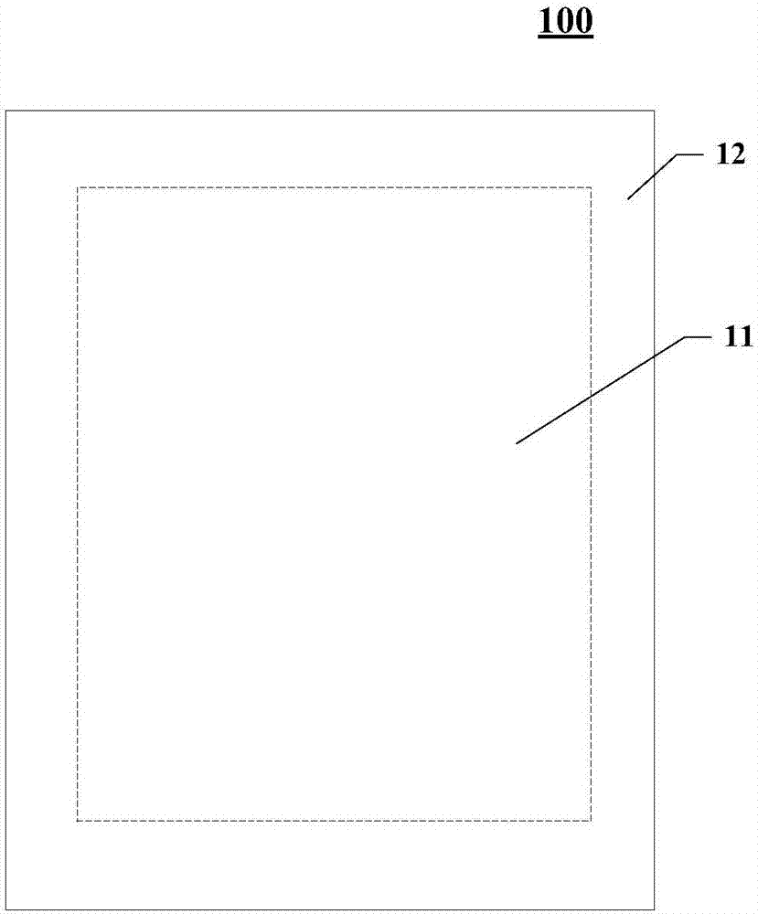
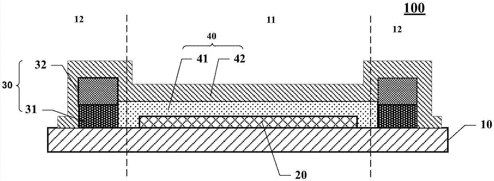
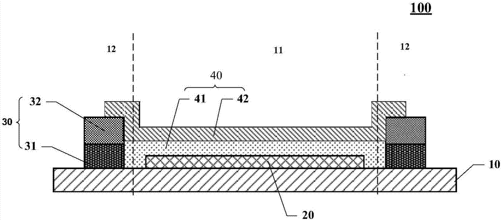

Image

  • Organic electroluminescence device
  • Organic electroluminescence device
  • Organic electroluminescence device

Examples


Embodiment Construction

[0058] Certain terms are used, for example, in the description and claims to refer to particular components. Those skilled in the art should understand that hardware manufacturers may use different terms to refer to the same component. The specification and claims do not use the difference in name as a way to distinguish components, but use the difference in function of components as a criterion for distinguishing. As mentioned throughout the specification and claims, "comprising" is an open term, so it should be interpreted as "including but not limited to". "Approximately" means that within an acceptable error range, those skilled in the art can solve the technical problem within a certain error range and basically achieve the technical effect. In addition, the term "coupled" herein includes any direct and indirect electrical coupling means. Therefore, if it is described that a first device is coupled to a second device, it means that the first device may be directly elect...


PUM


Abstract

The invention discloses an organic electroluminescence device which comprises the components of a substrate; an electroluminescent structure which is arranged on the substrate and is located in a displaying area; at least one retaining wall which is arranged on the substrate and is arranged in a non-displaying area, wherein the retaining wall surrounds the displaying area; at least one retaining wall is successively arranged in a direction of departing from the displaying area, and the retaining walls comprise a first retaining wall which is adjacent with the displaying area; the first retaining wall comprises at least one stack structure, the stack structure comprises an organophilic material layer and an organo-hydrophobic material layer, the organo-hydrophobic material layer is arranged on one side, which is far from the substrate, of the organophilic material layer; and a thin-film packaging layer which comprises an organic film layer and an inorganic film layer, wherein the organic film layer is arranged in a space which is formed through surrounding the displaying area by the first retaining wall, and the inorganic film layer is arranged on the surface, which is far from the electroluminescent structure, of the organic film. According to the organic electroluminescence device, a good boundary of the organic film layer is formed and furthermore thickness at the boundary of the organic film layer is effectively controlled.

Description

technical field [0001] The present application relates to the field of display technology, in particular to an organic electroluminescent device. Background technique [0002] In recent years, Organic Light-Emitting Diode (OLED, Organic Light-Emitting Diode) has become a very advanced display industry at home and abroad. , fast response time, high luminous efficiency, thin panel thickness, large-size and bendable panels can be produced, simple manufacturing process, and low cost. [0003] OLED devices generally use active metals as cathodes, which are easy to react with water vapor and affect charge injection, and the organic light-emitting materials in the device will also chemically react with water and oxygen. These reactions reduce the performance and service life of OLED devices. Therefore, OLED devices need to use good packaging technology to isolate the intrusion of water vapor and oxygen. [0004] Thin Film Encapsulation (Thin Film Encapsulation) is a packaging met...

Claims


Application Information

Patent Timeline
Patent Type & Authority Applications(China)
IPC IPC(8): H01L51/52H01L27/32
CPCH10K59/00H10K50/8428H10K50/84H10K50/8426
Inventor 姜文鑫霍思涛
Owner SHANGHAI TIANMA MICRO ELECTRONICS CO LTD
Why Eureka
Eureka Blog
Learn More