Ceiling router

A technology for routers and ceilings, which is applied in the direction of transmission systems, antennas, rotating antennas, etc., to achieve the effect of improving performance

Inactive Publication Date: 2017-09-26
东莞质研工业设计服务有限公司
View PDF6 Cites 3 Cited by
  • Summary
  • Abstract
  • Description
  • Claims
  • Application Information

AI Technical Summary

Problems solved by technology

[0002] At present, more and more routers are installed on the ceiling to increase its radiation range, but due to the phase problem of the antenna itself, there are always weak areas and strong areas when the top of the router radiates downward, so if you can It is perfect to design a router whose antenna can swing as needed, or retract when not in use

Method used


Image

  • Ceiling router
  • Ceiling router
  • Ceiling router

Examples


Embodiment Construction

[0023] The present invention will be described in further detail below in conjunction with the accompanying drawings and specific embodiments, and the implementation scope of the present invention is not limited thereto.

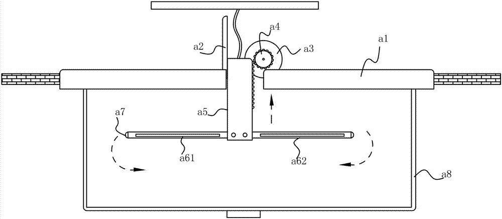
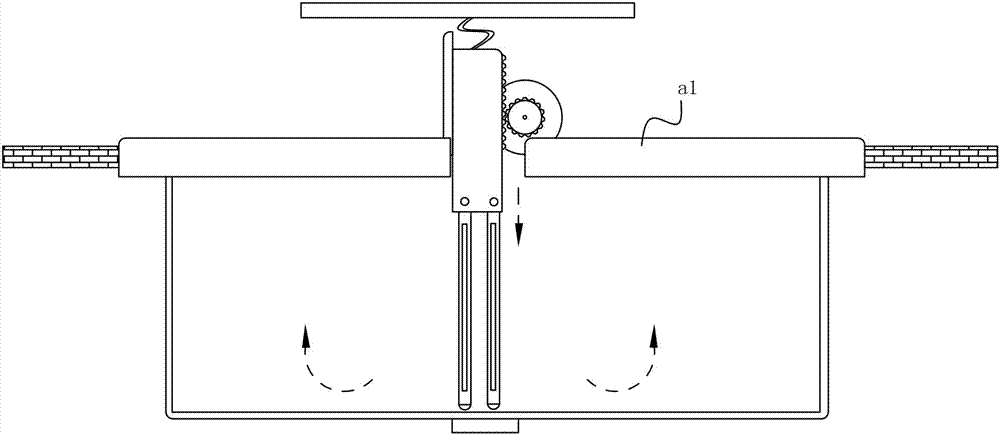
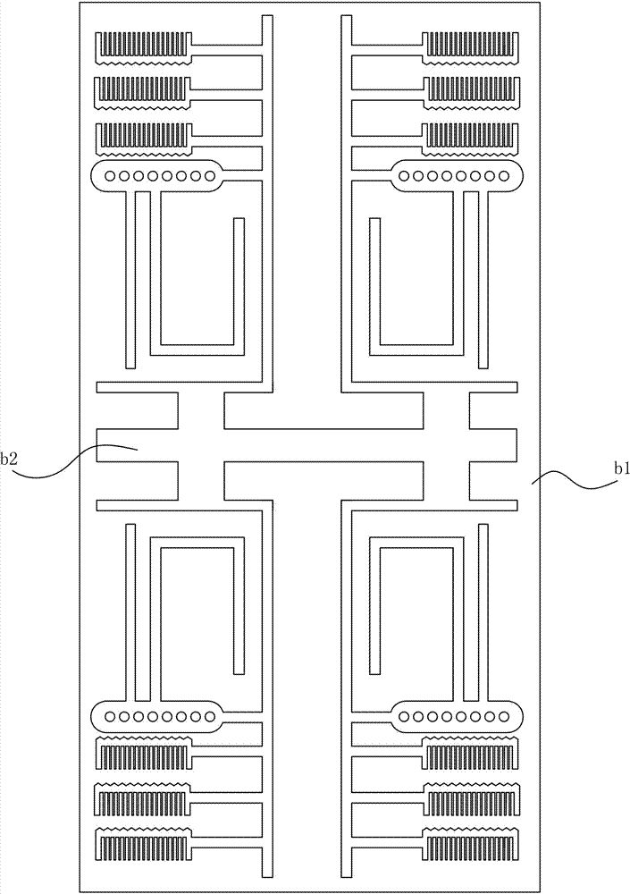
[0024] like Figure 1 to Figure 7 , the ceiling router described in this embodiment includes a disk frame a1 clamped on the ceiling, a through hole is provided in the middle of the disk frame a1, and a slide rail a2 is located on the top surface of the disk frame a1; It includes a longitudinal frame a5, one side of the longitudinal frame a5 is slidingly connected with the slide rail a2, and the other side is provided with a rack; the top surface of the disc frame a1 is also provided with a drive motor a3, and the power output end of the drive motor a3 is provided with Gear a4, the gear a4 meshes with the rack; the lower end of the longitudinal frame a5 is provided with a first servo motor and a second servo motor; it also includes a first antenna board and a...


PUM


Abstract

The invention discloses a ceiling router. The ceiling router comprises a disc rack clamped on a ceiling, wherein a via hole is formed in the center of the disc rack; the ceiling router further comprises a slide rail located on the top surface of the disc rack and a longitudinal rack, one side of the longitudinal rack is in sliding connection with the track of the slide rail, and a rack is arranged on the other side; a driving motor is further arranged on the top surface of the disc rack, and a gear is arranged at a power output end of the driving motor and meshed with the rack; a first servo motor and a second servo motor are arranged at the lower end of the longitudinal rack; the ceiling router further comprises a first antenna board and a second antenna board; the first antenna board and the second antenna board are fixedly connected with power output ends of the first servo motor and the second servo motor respectively; microstrip antennas are arranged in both the first antenna board and the second antenna board; by means of folding of the first antenna board and the second antenna board, the ceiling router can be spread when used and can be retracted when not used, and phase change and radiation direction can be adjusted as required, and router performance is improved.

Description

technical field [0001] The invention relates to a ceiling router. Background technique [0002] At present, more and more routers are installed on the ceiling to increase its radiation range, but due to the phase problem of the antenna itself, there are always weak areas and strong areas when the top of the router radiates downward, so if you can It would be perfect to design a router whose antennas can swing as needed, or retract when not in use. Contents of the invention [0003] The object of the present invention is to overcome the above-mentioned disadvantages and provide a ceiling router. [0004] In order to achieve the above object, the specific solution of the present invention is as follows: a suspended ceiling router, including a disc frame clamped on the suspended ceiling, a through hole is arranged in the middle of the disc frame, and a sliding frame positioned on the top surface of the disc frame is also included. It also includes a longitudinal frame, one ...

Claims


Application Information

Patent Timeline
IPC IPC(8): H01Q1/08H01Q1/22H01Q1/38H01Q3/06H04L12/771H04L45/60
CPCH01Q1/084H01Q1/22H01Q1/38H01Q3/06H04L45/60
Inventor 商顺超
Owner 东莞质研工业设计服务有限公司
Why Eureka
Try Eureka