Locally powered optical communication network

A technology of optical signal and communication section, applied in the field of optical communication network, can solve the problems of no power and limited bandwidth

Active Publication Date: 2017-09-26
GOOGLE LLC
View PDF6 Cites 0 Cited by
  • Summary
  • Abstract
  • Description
  • Claims
  • Application Information

AI Technical Summary

Problems solved by technology

[0004] The present disclosure addresses the limitations of traditional transoceanic fiber optic cables without the disadvantages of limited power and bandwidth

Method used


Image

  • Locally powered optical communication network
  • Locally powered optical communication network
  • Locally powered optical communication network

Examples


Embodiment Construction

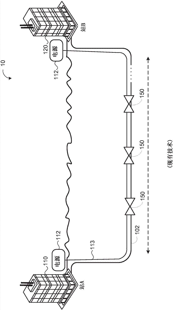
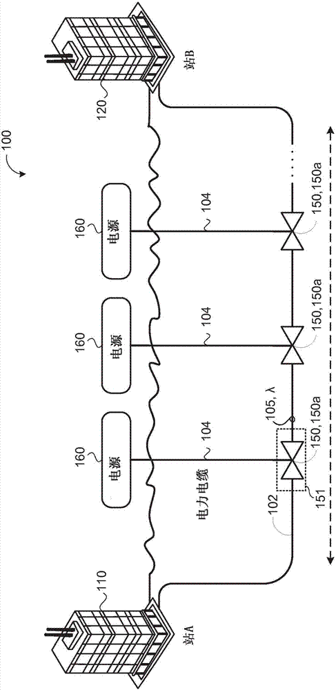
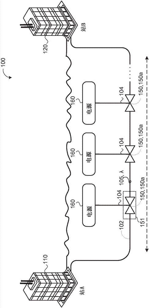
[0030] refer to figure 2 , the optical communication system 100 includes first and second trunk terminals 110 , 120 (also referred to as stations) coupled to a communication trunk 102 . A coupling may be any connection, link, etc. by which a signal carried by one system element is passed to the "coupled" element. Coupled elements may not necessarily be directly connected to each other and may be separated by intermediate components or devices that may manipulate or modify signals. Communications backbone 102 may include a plurality of fiber optic cable segments 102, 102a through 102n (eg, submarine cables) that carry optical signals 105 on associated optical channels / wavelengths λ.

[0031] Each fiber optic cable segment 102 may include: one or more sections of fiber optic cable comprising fiber optic pairs, and one or more of the transmission paths providing for bidirectional communication of optical signals 105 between first and second trunk terminals 110, 120. A pluralit...


PUM


Abstract

An optical system (100) for a locally powered optical communication network includes a first trunk terminal (110) emitting an optical signal (105, 105 c), a second trunk terminal (120) receiving the optical signal, a communication trunk (102, 102c), an intermediate unit (151) and a power source (160). The communication trunk is disposed along a floor of a body of water and couples the first trunk terminal to the second trunk terminal. The communication trunk transmits the optical signal from the first trunk terminal to the second trunk terminal. The intermediate unit is connected to the communication trunk between the first and second trunk terminals. The intermediate unit receives the emitted optical signal from the first trunk terminal, amplifies the received optical signal and sends the amplified optical signal to the second trunk. The power source powers the intermediate.

Description

technical field [0001] The present disclosure relates to a locally powered optical communications network, such as by using power sources along transoceanic fiber optic cables. Background technique [0002] Submarine optical communication cables are optical cables laid on the seabed connecting land-based stations. Optical communication cables carry signals across oceans, allowing ocean-crossing cables to communicate between different continents. Each transoceanic submarine cable includes multiple pairs (up to 8 pairs) of optical fibers; each pair has one optical fiber in each direction. Subsea optical communication cables are divided into sections, each section connected to the other sections via subsea repeaters. When a signal is carried across an ocean, the signal may lose some of its power. Each subsea repeater includes multiple erbium-doped fiber amplifiers (EDFAs), one for each direction of signal on each fiber. Each EDFA has a gain sufficient to compensate for the ...

Claims


Application Information

Patent Timeline
Patent Type & Authority Applications(China)
IPC IPC(8): H04B10/291H04B10/50H04B10/80H04J14/02
CPCH04B10/291H04B10/503H04B10/801H04J14/0201H04B10/807H04B10/808H04J14/0213H04B10/2916H04B10/2575
Inventor 瓦莱·卡马洛夫约瑟夫·弗里兰安德鲁·梅特卡夫
Owner GOOGLE LLC
Why Eureka
Try Eureka