Equipment fault diagnosis method and device based on storage and calculation integrated technology

A technology for equipment faults and diagnostic devices, which is applied in the direction of measuring devices, machine/structural component testing, instruments, etc., can solve problems such as difficult implementation, poor low-frequency response performance, non-stationary, etc., to save line space, improve accuracy, The effect of high recognition rate

Inactive Publication Date: 2020-12-11
李文彬
View PDF0 Cites 0 Cited by
  • Summary
  • Abstract
  • Description
  • Claims
  • Application Information

AI Technical Summary

Problems solved by technology

However, the above processing methods also have defects. For example, the signal filtering method generally cannot obtain information outside the filter passband at the same time; the time-domain averaging method requires the signal to be stable and strictly sampled periodically, which is limited by the non-stationary operating conditions in practical applications and is difficult to obtain. Implementation; the adaptive denoising method requires that the signal and noise are stable and independent of each other. In the field, the signal and noise are not only non-stationary, but also have different degrees of correlation. Not ideal, affecting the accuracy of diagnosing hidden dangers of equipment failure
[0005] However, in the monitoring method in the prior art, the piezoelectric sensor used is bulky, the power supply voltage is high, the battery power supply is inconvenient, and the low frequency response performance is poor
Data analysis and determination of operating status need to be judged based on workers' experience, which is highly subjective and the judgment results are inaccurate, so it is not suitable for mass promotion

Method used


Image

  • Equipment fault diagnosis method and device based on storage and calculation integrated technology

Examples


Embodiment Construction

[0020] The specific implementation manner of the present invention will be further described below in conjunction with the accompanying drawings. Wherein the same components are denoted by the same reference numerals. It should be noted that the words "front", "rear", "left", "right", "upper" and "lower" used in the following description refer to the directions in the drawings, and the words "inner" and "outer ” refer to directions towards or away from the geometric center of a particular part, respectively.

[0021] In order to make the content of the present invention more clearly understood, the technical solutions in the embodiments of the present invention will be clearly and completely described below in conjunction with the drawings in the embodiments of the present invention.

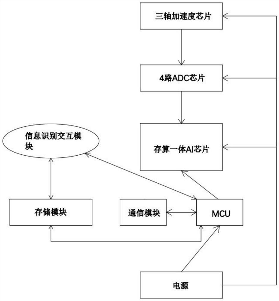
[0022] like figure 1 As shown, a device fault diagnosis device based on integrated storage and computing technology includes a three-axis acceleration chip, 4 ADC chips, an MCU chip, and a pow...


PUM


Abstract

The invention provides an equipment fault diagnosis method and device based on a storage and calculation integrated technology, and the device comprises a three-axis acceleration chip, four ADC chips,an MCU chip, and a power supply module, the MCU chip is connected with a storage and calculation integrated AI chip and a communication module, and the three-axis acceleration chip is in circuit connection with the four ADC chips. The four ADC chips are in circuit connection with the storage and calculation integrated AI chip, the power supply module is connected with the three-axis accelerationchip, the four ADC chips, the MCU chip, the AI chip and the communication module for power supply, the communication module is connected with a storage module and an information identification interaction module, and the communication module is in circuit connection with the information identification interaction module. Fault determination and diagnosis are achieved through signal acquisition ofthe three-axis acceleration chip and information processing of the storage and calculation integrated AI chip and the MCU chip. The invention provides an equipment fault diagnosis method and device based on a storage and calculation integrated technology, and the method and device have the advantages of low cost, low power consumption, high efficiency, high calculation capability and high recognition rate.

Description

technical field [0001] The invention relates to the field of fault diagnosis, in particular to a device fault diagnosis method and device based on integrated storage and calculation technology. Background technique [0002] Various large-scale equipment are more and more widely used in daily life and production. In order to detect potential equipment failures in advance and obtain equipment operating status, people have invented equipment failure detection methods that use mechanical equipment vibration signals as state parameters. [0003] At present, the methods of using equipment vibration signals to detect potential equipment failures are generally traditional signal processing methods based on stationary processes, such as signal filtering, time-domain averaging, and adaptive noise reduction methods. The adoption of these processing methods makes the early detection of faults There have been many advances in diagnosis. However, the above processing methods also have de...

Claims


Application Information

Patent Timeline
Patent Type & Authority Applications(China)
IPC IPC(8): G01M99/00
CPCG01M99/004G01M99/005
Inventor 李文彬
Owner 李文彬
Why Eureka
Try Eureka