Oil storage tank cleaning system and method

A technology for cleaning systems and oil storage tanks, applied in the field of oil storage tank cleaning systems, can solve the problems of fast cleaning speed, low efficiency, insufficient cleaning equipment, etc., to prevent unstable work, improve cleaning efficiency, and facilitate cleaning.

Active Publication Date: 2017-09-29
宋局
View PDF3 Cites 3 Cited by
  • Summary
  • Abstract
  • Description
  • Claims
  • Application Information

AI Technical Summary

Problems solved by technology

In my country's current situation, because advanced cleaning equipment is expensive, it is impossible to equip it in equal proportions. At the same time, the manual cleaning cycle is long, the risk is high, and the efficiency is low. Combined with the actual situation, many scholars have propos

Method used


Image

  • Oil storage tank cleaning system and method
  • Oil storage tank cleaning system and method
  • Oil storage tank cleaning system and method

Examples


Embodiment Construction

[0049] Specific embodiments of the present invention will be illustrated below with reference to the accompanying drawings.

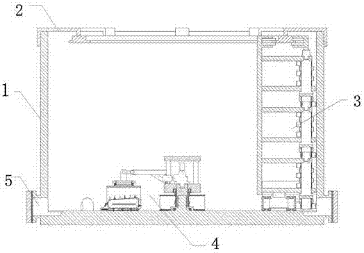
[0050] Such as figure 1 As shown, the oil storage tank cleaning system of the present invention is arranged in the tank body 1 of the oil storage tank, including: a rail frame 2 , a side wall cleaning device 3 and a bottom surface cleaning device 4 .

[0051] Wherein, the rail frame 2 is mounted on the top opening of the oil storage tank, the side wall cleaning device 3 is mounted on the rail frame 2 , and the side wall cleaning device 3 is movable relative to the rail frame 2 .

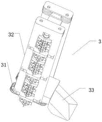
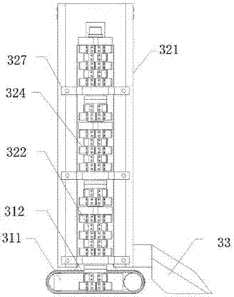
[0052] refer to Figure 2 to Figure 7 , the side wall cleaning device 3 includes a chassis 31 and a side wall cleaning main body 32, the chassis 31 includes a first traveling device 311 and a bottom plate 312, and the bottom plate 312 is fixed on the first traveling device 311 for supporting the side wall cleaning main body 32. The first traveling device 311 can be a crawler...


PUM


Abstract

The invention provides an oil storage tank cleaning system. The system comprises a guide rail rack (2), a sidewall cleaning device (3) and a bottom surface cleaning device (4), wherein the guide rail rack (2) is mounted to an opening in the top part of an oil storage tank; the sidewall cleaning device (3) is mounted to the guide rail rack (2) and can move relative to the guide rail rack (2); the bottom surface cleaning device (4) comprises a control unit (41) which is positioned in a center area of the bottom surface of the oil storage tank, and a cleaning unit (42) which is connected to the control unit (41) and used for cleaning the bottom surface of the oil storage tank. With the adoption of the system, the oil storage tank can be regularly cleaned without artificial interference. The invention also provides an oil storage tank cleaning method utilizing the abovementioned oil storage tank cleaning system.

Description

technical field [0001] The present invention relates to the technical field of oil storage tank cleaning, in particular to an oil storage tank cleaning system and method. Background technique [0002] In the process of crude oil extraction, tiny particles in the oil reservoir, a small amount of mechanical impurities, sand, soil, heavy metal salts, and heavy oily substances such as paraffin and asphalt will naturally sink due to their high specific gravity. When crude oil is stored in the oil storage tank When it accumulates at the bottom of the oil tank, it forms a black and thick gelatinous substance layer, which is the bottom sludge of the oil tank. The sludge at the bottom increases with the continuous storage and transportation time, which seriously affects the storage and transportation production of the oil tank. It must be regularly to clear. [0003] In addition, when the oil product is upgraded or replaced with different oil products, the remaining oil in the tank ...

Claims


Application Information

Patent Timeline
IPC IPC(8): B08B9/087B08B13/00
CPCB08B9/087B08B13/00
Inventor 郑立群
Owner 宋局
Why Eureka
Try Eureka