Automatic processing assembling device for screwdriver

A technology of automatic processing and assembly device, applied in positioning devices, metal processing, metal processing equipment, etc., can solve the problems of low concentricity between screwdriver shank and screwdriver handle, high product scrap rate, and achieve automatic assembly and high degree of automation. , the effect of increasing profit margins

Active Publication Date: 2017-09-29
舟山市敏瑞科技咨询有限公司
View PDF6 Cites 6 Cited by
  • Summary
  • Abstract
  • Description
  • Claims
  • Application Information

AI Technical Summary

Problems solved by technology

[0002] A screwdriver is composed of a screwdriver handle and a screwdriver shaft. Instrument screwdrivers are generally obtained by inserting the screwdriver shaft into the screwdriver handle. In order to improve profit margins and reduce manufacturing costs, currently, the screwdriver shafts and screwdriver handles of instrument screwdrivers on the market are made of different metal materials. During the assembly process of the screwdriver handle and the screwdriver shaft, the screwdriver handle needs to be positioned twice, resulting in a low concentricity between the screwdriver shaft and the screwdriver handle, resulting in a high product scrap rate

Method used


Image

  • Automatic processing assembling device for screwdriver
  • Automatic processing assembling device for screwdriver
  • Automatic processing assembling device for screwdriver

Examples


Embodiment Construction

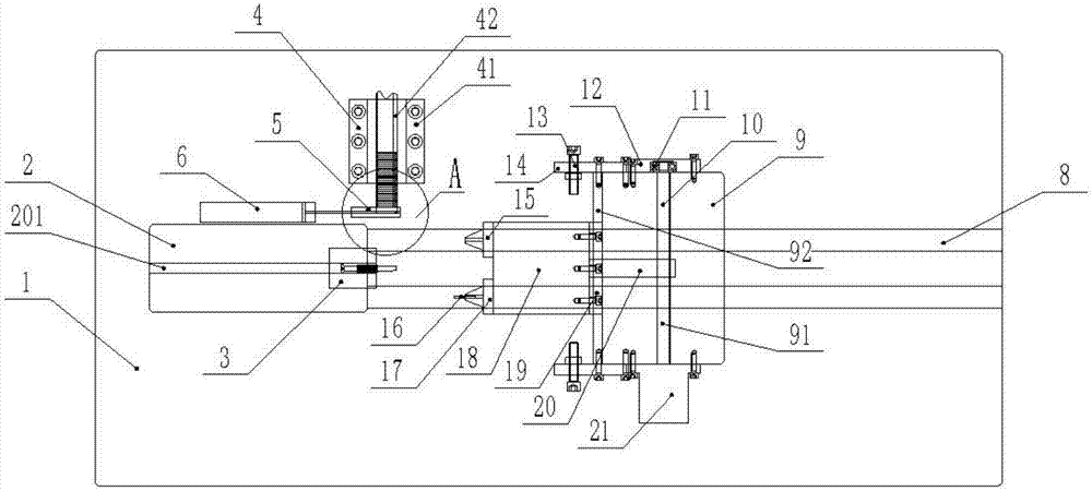
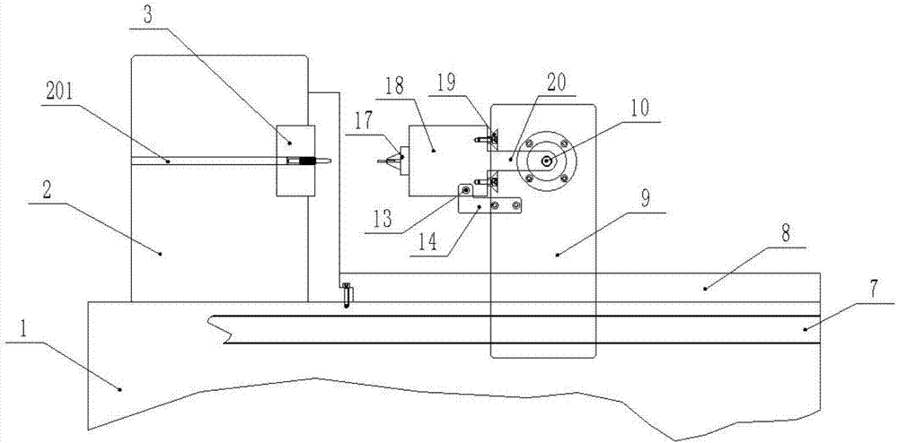
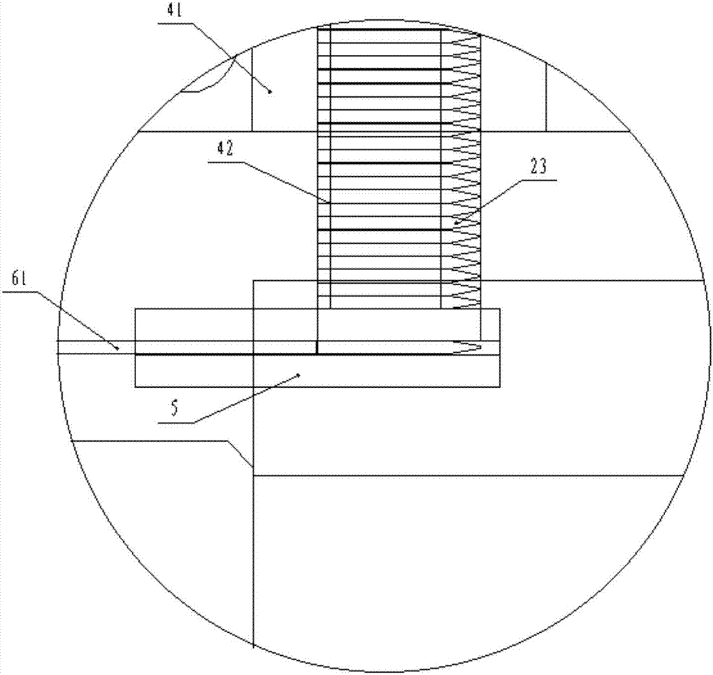
[0030] As shown in the figure, a screwdriver automatic processing and assembling device according to the embodiment of the present invention includes: figure 1 , figure 2 As shown, the machine base 1 is equipped with a power screw 7, and the slideway 8 is symmetrically installed on the working surface of the machine base 1; the machine head 2 is fixed on the left side and the top of the machine base 1, and a horizontal discharge material Pipe 201; the pneumatic chuck 3 is fixed on the right side of the machine head 2, and the pneumatic chuck 3 is flush with the discharge pipe 201; the pneumatic chuck 3 can rotate freely; 4 comprises the flat feeder 41 and the flat feed track 42 above it ( Figure 5 shown); the top of the horizontal feeding mechanism 4 is connected with a vibrating feeding tray; as image 3 As shown, the discharge block 5 is fixed between the machine head 2 and the flat delivery mechanism 4, as Figure 4 As shown, the material pushing track 51 and the feedi...


PUM


Abstract

The invention discloses an automatic processing assembling device for a screwdriver. A machine head is fixedly arranged above the left side of a machine base; a discharge tube is processed in the machine head; a pneumatic chuck is fixedly arranged at the right side of the machine head; a horizontal feeding mechanism is mounted at one side of the machine head, and comprises a horizontal feeder and a horizontal feeding rail; a discharge block is fixedly arranged between the horizontal feeder and the machine head, and abuts against the horizontal feeding rail; an air cylinder is arranged at the left side of the discharge block; a slide path is mounted at the right side of the machine base; a knife rest is positioned on the slide path and is driven by a power lead screw; a processing through hole in the knife rest is used for mounting the lead screw; the inner side of the lead screw is limited by a cover plate, and the outer side of the lead screw is connected with a motor; a dovetail slot is processed in the wall surface at the left side of the knife rest; a tool bit is embedded into the dovetail slot from a slide bock, and is connected with the lead screw through a connecting block; a pneumatic chuck I and a pneumatic chuck II are mounted on the tool bit; a reducing drill bit is fixedly arranged on the pneumatic chuck I; a PLC controls the knife rest to move; after the reducing drill bit drills, the pneumatic chuck II drives out a screw cutter bar from a discharge block and is inserted into a cutter bar hole in an interference mode; and the automatic processing assembling device is compact in structure, realizes once positioning of the screw cutter shank, and is high in assembly precision.

Description

technical field [0001] The invention relates to a mechanical processing device, in particular to a screwdriver automatic processing and assembling device. Background technique [0002] A screwdriver is composed of a screwdriver handle and a screwdriver shaft. Instrument screwdrivers are generally obtained by inserting the screwdriver shaft into the screwdriver handle. In order to improve profit margins and reduce manufacturing costs, currently, the screwdriver shafts and screwdriver handles of instrument screwdrivers on the market are made of different metal materials. In the process of assembling the screwdriver handle and the screwdriver shaft, the screwdriver handle needs to be positioned twice, resulting in low concentricity between the screwdriver shaft and the screwdriver handle, resulting in a high product scrap rate. [0003] A screwdriver automatic processing and assembling device mentioned in the present invention solves the above-mentioned problems. Contents of ...

Claims


Application Information

Patent Timeline
Patent Type & Authority Applications(China)
IPC IPC(8): B23P19/027B23P19/00B23B41/00B23Q3/08
CPCB23B41/00B23P19/006B23P19/027B23Q3/08
Inventor 龚雅萍
Owner 舟山市敏瑞科技咨询有限公司
Why Eureka
Try Eureka