Plastic handle assembling machine

A technology for assembling machines and handles, applied in metal processing, metal processing equipment, manufacturing tools, etc., can solve the problems of reducing product quality and production efficiency, reducing skilled workers, assembly dislocation, etc., to improve product quality and production efficiency, reduce Operation difficulty and labor intensity, the effect of uniform force

Active Publication Date: 2017-09-29
湖南锐科机器人技术有限公司
View PDF7 Cites 6 Cited by
  • Summary
  • Abstract
  • Description
  • Claims
  • Application Information

AI Technical Summary

Problems solved by technology

[0002] In order to facilitate use and protect the safety of users, a plastic handle needs to be put on the handle of tool pliers, etc. Most factories still use the original pure manual assembly method to complete this process in the production process; the production steps are as follows: Workers hold the handle to be processed with one hand, and apply a certain amount of glue on the handle, and then use the other hand to put the heated plastic handle on the handle to be processed until the designated position, and then hang it on the cooling rack to cool down. Complete this process; the completion of the process depends on the technical proficiency level of the workers, including the assembly angle, assembly force, assembly efficiency, etc. At present, very few workers are willing to stay in this tedious operation position for a long time, resulting in the reduction of skilled workers. The production management of the factory has brought certain tests
[0003] Moreover, the labor intensity of the assembly production process is high, workers’ fingers are easily scratched, it is difficult to meet the specified requirements during the assembly process, and it is easy to produce inaccurate assembly or assembly misalignment, which greatly reduces product quality and production efficiency, and increases product quality. Scrap rate

Method used


Image

  • Plastic handle assembling machine
  • Plastic handle assembling machine
  • Plastic handle assembling machine

Examples


Embodiment Construction

[0029] In order to enable those skilled in the art to better understand the technical solution of the present invention, the present invention will be described in detail below in conjunction with the accompanying drawings. The description in this part is only exemplary and explanatory, and should not have any limiting effect on the protection scope of the present invention. .

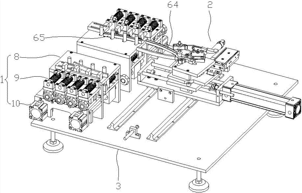
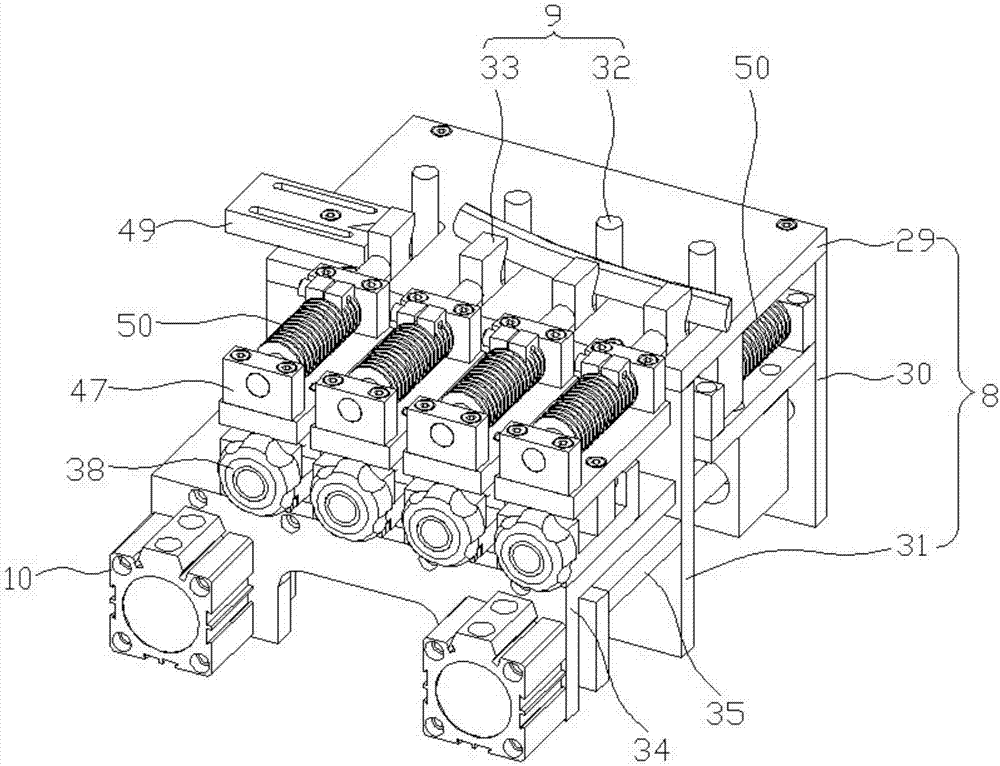
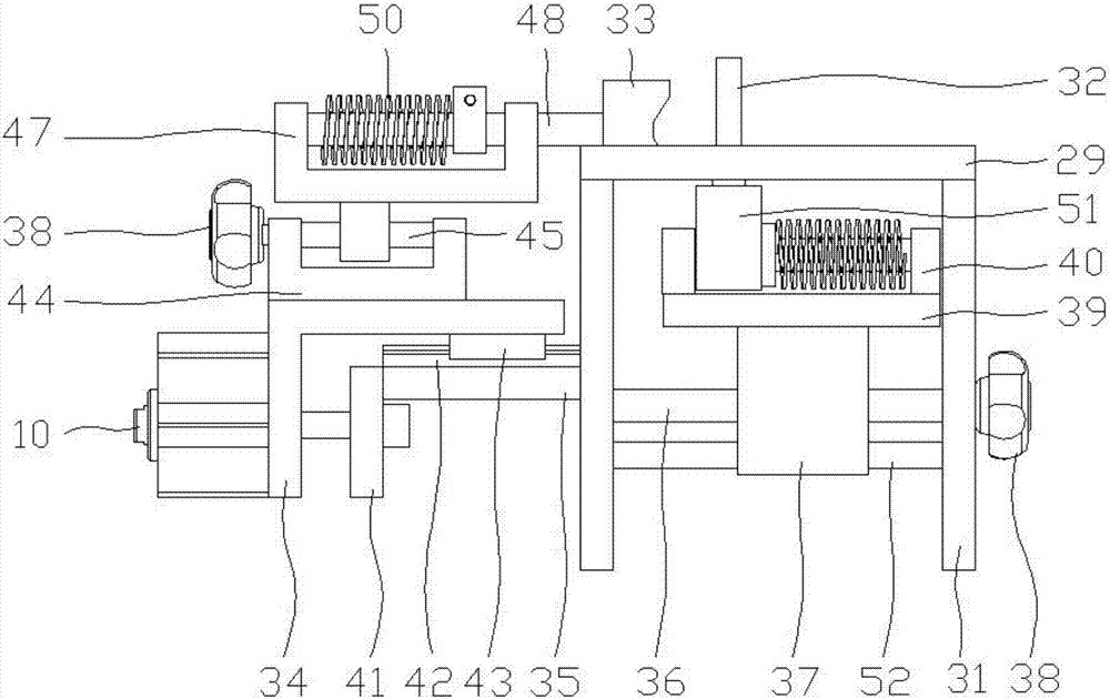
[0030] Such as Figure 1-Figure 8 As shown, the specific structure of the present invention is: it includes a plastic handle clamping mechanism 1, a workpiece clamping mechanism 2, and a control device, and the plastic handle clamping mechanism 1 and the workpiece clamping mechanism 2 are arranged on the installation platform 3; The workpiece clamping mechanism 2 includes a lateral movement mechanism 4, a vertical movement mechanism 5, a clamping table 6, and a clamping table swing mechanism 7, and the plastic handle clamping mechanism 1 includes a fixed frame 8, a movable clamping device 9, Push the ...


PUM


Abstract

The invention relates to a plastic handle assembling machine which comprises a plastic handle clamping mechanism, a workpiece clamping mechanism and a control device. The plastic handle clamping mechanism and the workpiece clamping mechanism are arranged on an installing platform; the workpiece clamping mechanism comprises a transverse movement mechanism, a vertical movement mechanism, a clamping table and a clamping table swing mechanism; and the plastic handle clamping mechanism comprises a fixing support, a movable type clamping device and a pushing air cylinder. According to the aim, the plastic handle assembling machine is provided, a plastic handle and a workpiece are clamped by the machine, the workpiece and the plastic handle are assembled through a driving device, and therefore it can be guaranteed that the handle is even in stress and free of slippage in the assembling process, the operation difficulty and the labor intensity of workers are reduced, and the product quality and the production efficiency are improved.

Description

technical field [0001] The invention belongs to the field of assembly and clamping, in particular to a plastic handle assembly machine. Background technique [0002] In order to facilitate use and protect the safety of users, a plastic handle needs to be put on the handle of tool pliers, etc. Most factories still use the original pure manual assembly method to complete this process in the production process; the production steps are as follows: Workers hold the handle to be processed with one hand, and apply a certain amount of glue on the handle, and then use the other hand to put the heated plastic handle on the handle to be processed until the designated position, and then hang it on the cooling rack to cool down. Complete this process; the completion of the process depends on the technical proficiency level of the workers, including the assembly angle, assembly force, assembly efficiency, etc. At present, very few workers are willing to stay in this tedious operation pos...

Claims


Application Information

Patent Timeline
Patent Type & Authority Applications(China)
IPC IPC(8): B23P19/04
CPCB23P19/04Y02W30/62
Inventor 王志刚周胜强刮国良
Owner 湖南锐科机器人技术有限公司
Why Eureka
Try Eureka