Die assembly for double-stage differential pressure type capillary rheometers

A capillary rheometer and die technology, applied in the field of rheometer, can solve the problems of low experimental efficiency and low test pressure, and achieve the effect of improving experimental efficiency

Inactive Publication Date: 2017-09-29
BEIJING UNIV OF CHEM TECH
View PDF6 Cites 2 Cited by
  • Summary
  • Abstract
  • Description
  • Claims
  • Application Information

AI Technical Summary

Problems solved by technology

At present, the traditional capillary rheometer can only measure one set of viscosity data in a single experiment, the experiment efficiency is not high, and the test pressure is relatively low

Method used


Image

  • Die assembly for double-stage differential pressure type capillary rheometers
  • Die assembly for double-stage differential pressure type capillary rheometers
  • Die assembly for double-stage differential pressure type capillary rheometers

Examples


Embodiment 1

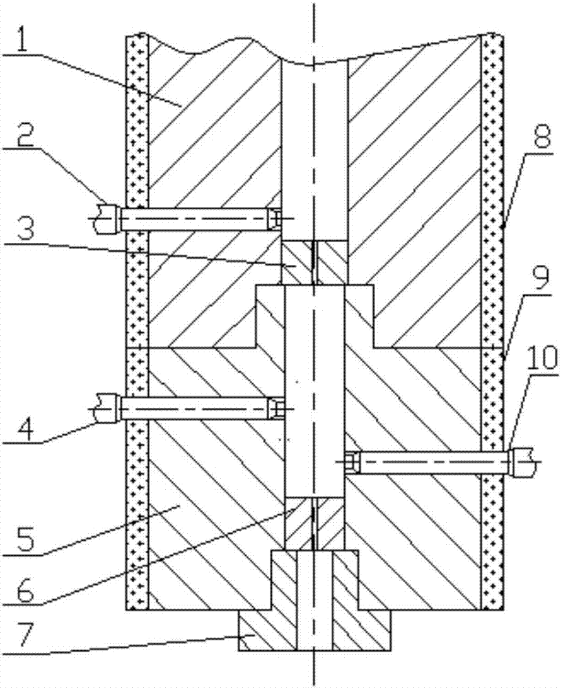
[0032] Such as figure 1 As shown, a die assembly of a two-stage partial pressure capillary rheometer.

[0033] The die assembly includes a first barrel 1 and a second barrel A5, the first barrel 1 is on the top, the second barrel A5 is on the bottom, and the outer wall of the first barrel 1 and the outer wall of the second barrel A5 are respectively provided with The first heating jacket 8 and the second heating jacket 9; the first barrel 1 and the second barrel A5 are connected through a threaded structure; the end of the first barrel 1 is provided with an internal thread groove, and the groove is connected to the inner surface of the first barrel. The cavity is concentric, and the diameter of the groove is greater than the diameter of the inner cavity; the top of the second barrel A5 is provided with an external thread boss, the boss is concentric with the inner cavity of the second barrel, and the boss is concentric with the inner thread groove of the first barrel. Coopera...

Embodiment 2

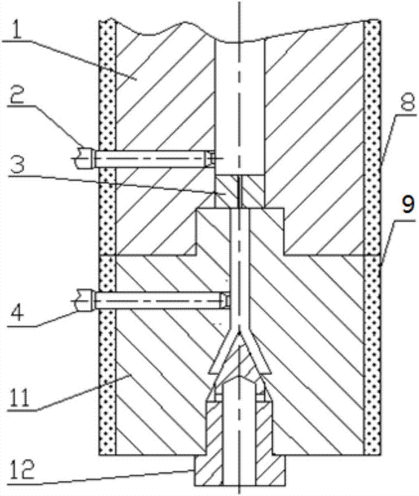
[0040] Such as figure 2 As shown, a die assembly of a two-stage partial pressure capillary rheometer.

[0041] The die assembly includes a first barrel 1 and a second barrel B11, the first barrel 1 is on the top, the second barrel B11 is on the bottom, and the outer wall of the first barrel 1 and the outer wall of the second barrel B11 are respectively provided with The first heating jacket 8 and the second heating jacket 9; the first barrel 1 and the second barrel B11 are connected through a threaded structure; the end of the first barrel 1 is provided with an internal thread groove, and the groove is connected to the inner surface of the first barrel. The cavity is concentric, and the diameter of the groove is larger than the diameter of the inner cavity; the top of the second barrel B11 is provided with an external thread boss, the boss is concentric with the inner cavity of the second barrel, and the boss is concentric with the inner thread groove of the first barrel Coo...


PUM


Abstract

The invention provides a die assembly for double-stage differential pressure type capillary rheometers. The die assembly comprises a first barrel and a second barrel, the end of the first barrel is provided with a cylindrical socket, the socket is concentric with the cavity of the first barrel, and moreover, the diameter of the socket is greater than the diameter of the cavity; the top end of the second barrel is provided with a cylindrical boss, the boss is concentric with the cavity of the second barrel, the boss matches the diameter of the socket of the first barrel, and the boss of the second barrel is inserted in the socket of the first barrel; a first die is arranged in the end of the cavity of the first barrel, a first pressure sensor is arranged on the barrel wall close to the first die, and the first pressure sensor runs through a first heating jacket and the wall of the first barrel to communicate with the cavity. The die assembly not only can increase the pressure of the inlet of the first die, but also can test the viscosity of high polymer melt under two different pressures each time, so that the efficiency of an experiment is greatly increased, and the die assembly can also compare the viscosity changes of the high polymer melt under different pressures at the same time.

Description

technical field [0001] The present invention relates to the field of rheometers, and furthermore, relates to a die part, a die part of a two-stage partial pressure capillary rheometer which can test the viscosity of high polymer melt under high pressure and improve the experimental efficiency at the same time. module components. Background technique [0002] In recent years, the precision processing and molding technology of polymer materials has developed rapidly, and the fluidity and viscoelasticity of polymers in a viscous flow state have become the primary considerations for the exploration of its molding processing technology. Different from basic rheology, the research of processing rheology is based on the simulation of polymer melt flow characteristics under processing conditions, so we need to change the temperature of polymer melt flow as much as possible , pressure, and flow rate parameters to gain a broader understanding of the rheological properties of polymers...

Claims


Application Information

Patent Timeline
Patent Type & Authority Applications(China)
IPC IPC(8): G01N11/00
CPCG01N11/00
Inventor 林祥任冬云刘炯张凯
Owner BEIJING UNIV OF CHEM TECH
Why Eureka
Try Eureka