Feeding deep-sea optical cable

A deep-sea, optical cable technology, applied in the direction of light guide, optics, optical components, etc., can solve the problems of difficult filling of water blocking materials, long maintenance time, poor radial water blocking ability, etc., so as to improve the longitudinal water blocking ability and reduce maintenance. cost, the effect of improving impact resistance

Inactive Publication Date: 2017-09-29
JIANGSU HENGTONG MARINE CABLE SYST CO LTD
View PDF6 Cites 9 Cited by
  • Summary
  • Abstract
  • Description
  • Claims
  • Application Information

AI Technical Summary

Problems solved by technology

[0003] ①. It is very difficult to fill the water-blocking material, it is difficult to fill it full, and the influence of seawater itself on the conventional water-blocking material, resulting in poor longitudinal water-blocking ability of the cable. Once the optical cable breaks during use, the length of maintenance required is large. , long maintenance time;
[0004] ② Poor impact resistance and flattening resistance, insufficient mechanical tensile properties of the cable core, unable to meet the deployment and recovery tension requirements of the deep sea, and cannot be directly applied to the deep water environment of the deep sea;
[0005] ③ The radial water resistance of the cable is poor, and the edge of the copper strip is prone to warping during the manufacturing process, thereby causing damage to the sheath layer and reducing the insulation performance of the submarine cable;
[0006] ④. The outer longitudinal copper tape of the optical unit and the outer sheath are used as the cable core. Since there is no inner armor protection, the cable core is easily twisted during the production process, which poses a greater risk to the core unit of the submarine optical cable - the optical fiber.

Method used


Image

  • Feeding deep-sea optical cable

Examples


Embodiment

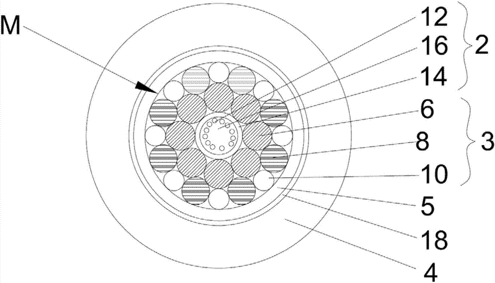
[0039] like figure 1 As shown, this embodiment discloses a feeding deep-sea optical cable, including an optical unit 2, an armor layer 3 twisted outside the optical unit 2, a feed layer 5 coated on the outside of the armor layer 3, and a coating The adhesive layer 18 on the outer side of the feed layer 5 and the high-density polyethylene insulating layer 4 covering the outer side of the adhesive layer 18 .

[0040] The optical unit 2 includes an optical fiber 12 and a stainless steel tube 14 coated on the outside of the optical fiber 12 , and the gap between the optical fiber 12 and the stainless steel tube 14 is filled with fiber paste 16 .

[0041] The armor layer 3 includes an inner twisted layer and an outer twisted layer, the inner twisted layer is twisted outside the stainless steel pipe 14, the outer twisted layer is twisted outside the inner twisted layer, and the feed layer 5 is covered outside the outer twisted layer;

[0042] The above-mentioned inner twisted layer...


PUM


Abstract

The invention provides a feeding deep-sea optical cable, which comprises an optical unit, an armored layer, a feeding layer and an insulating layer, and is characterized in that the armored layer comprises an inner stranded layer and an outer stranded layer, the inner stranded layer is provided with a plurality of first stranding metal wires, the outer stranded layer is provided with a plurality of second stranding metal wires and a plurality of third stranding metal wires, the second stranding metal wires and the third stranding metal wires are alternatively arranged in sequence, and the diameter of the third stranding metal wires is less than the diameter of the second stranding metal wires; the plurality of first stranding metal wires are stranded outside the optical unit, the second stranding metal wires and the third stranding metal wires are stranded on the first stranding metal wires at intervals, the third stranding metal wires are stranded on the second stranding metal wires, and stranding directions are the same. The feeding deep-sea optical cable improves the impact resistance, the flattening resistance and the mechanical stretching performance of submarine cables, improves the longitudinal water blocking performance and the radial water blocking performance of the submarine cables, reduces the manufacturing cost and maintenance cost of the submarine cables, reduces damages for an optical fiber in the manufacturing process and improves the insulating performance of the submarine cables.

Description

technical field [0001] The invention belongs to the technical field of submarine cables, and in particular relates to a feeding deep-sea optical cable. Background technique [0002] Submarine optical cable is a high-end variety with the highest technical content, the most difficult manufacturing, and the most complex application environment in the "big family" of cable products. Trans-ocean intercontinental communication, national defense communication, marine exploration and monitoring network construction. The current common deep-sea optical cables have the following deficiencies: [0003] ①. It is very difficult to fill the water-blocking material, it is difficult to fill it full, and the influence of seawater itself on the conventional water-blocking material, resulting in poor longitudinal water-blocking ability of the cable. Once the optical cable breaks during use, the length of maintenance required is large. , long maintenance time; [0004] ② Poor impact resistan...

Claims


Application Information

Patent Timeline
Patent Type & Authority Applications(China)
IPC IPC(8): G02B6/44
CPCG02B6/4427G02B6/443
Inventor 商庆亮胥国祥沈韦韦陈小龙余文慧冯聪王雄宋敬涛
Owner JIANGSU HENGTONG MARINE CABLE SYST CO LTD
Why Eureka
Try Eureka