
LED light source with stable light color

An LED light source and stabilization technology, applied in the field of LED light source, can solve the problems of high cost, complex system, and insignificant light source stabilization effect, and achieve the effect of low manufacturing cost and simple structure

Pending Publication Date: 2017-09-29
GUANGDONG INST OF SEMICON IND TECH
View PDF5 Cites 4 Cited by
  • Summary
  • Abstract
  • Description
  • Claims
  • Application Information

AI Technical Summary

Problems solved by technology

The above solutions can improve the luminosity and chromaticity stability of the LED light source to a certain extent, but these methods have problems such as complex system, high cost, or not obvious stabilization effect of the light source.

Method used


Image

  • LED light source with stable light color
  • LED light source with stable light color
  • LED light source with stable light color

Examples


Embodiment 1

[0022] This embodiment ignores the influence of the chromaticity and brightness of each color LED with the working time, has the advantages of simple structure and low cost, and can be widely used in application fields that do not require very high light color stability.

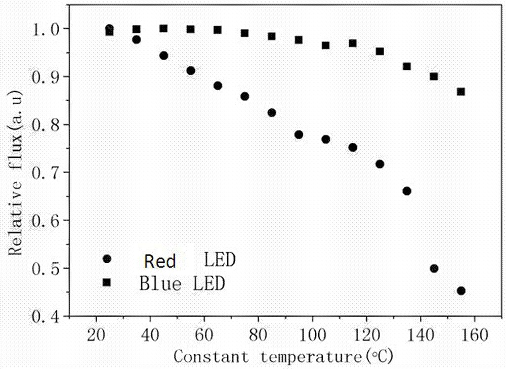
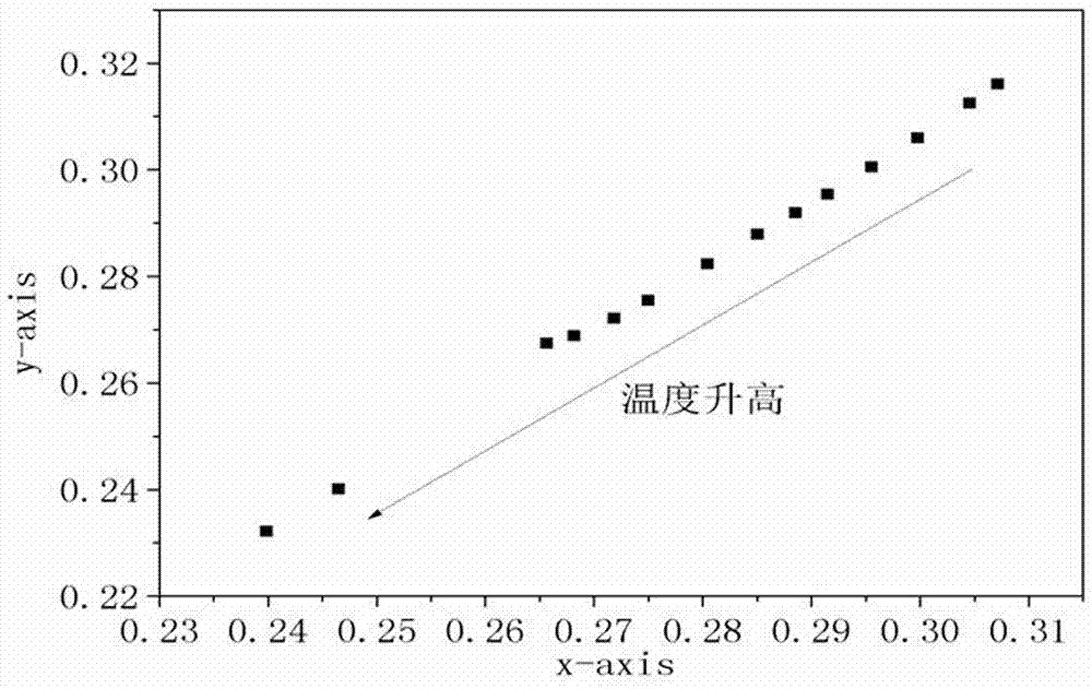
[0023] Step 1: Test the selected LED lamp bead data. The working current of each LED lamp bead is constant at 350mA, and the following data of each LED is tested through external temperature changes: ①The relationship between the brightness of the LED and the temperature of the node (such as figure 2 shown), ②CIE chromaticity coordinates change relationship with junction temperature (such as image 3 shown), ③The relationship between LED junction temperature and LED operating voltage (such as Figure 4 shown).

[0024] Step two:

[0025] The micro-control unit stores the data measured in step 1, and the micro-control unit regularly reads the operating voltage of each color LED measured by the voltage det...

Embodiment 2

[0029] In this embodiment, the influence of the chromaticity and brightness of each color LED along with the working time is increased, and the chromaticity and brightness stability accuracy of the mixed light source is higher, which can be widely used in high-end application fields.

[0030] On the basis of Example 1, when testing the data of the selected LED lamp bead, it is added to test the change of the brightness and chromaticity coordinates of each color LED lamp bead with the working time. The microcontroller unit stores this data.

[0031] The micro-control unit regularly reads the voltage detection and timer data, and calculates the LED brightness of each color according to the relationship between the brightness of the LED and the relationship between the CIE chromaticity coordinates and the temperature of the node and the relationship between the brightness of the LED and the relationship between the CIE chromaticity coordinates and the working hours. Changes in br...


PUM


Abstract

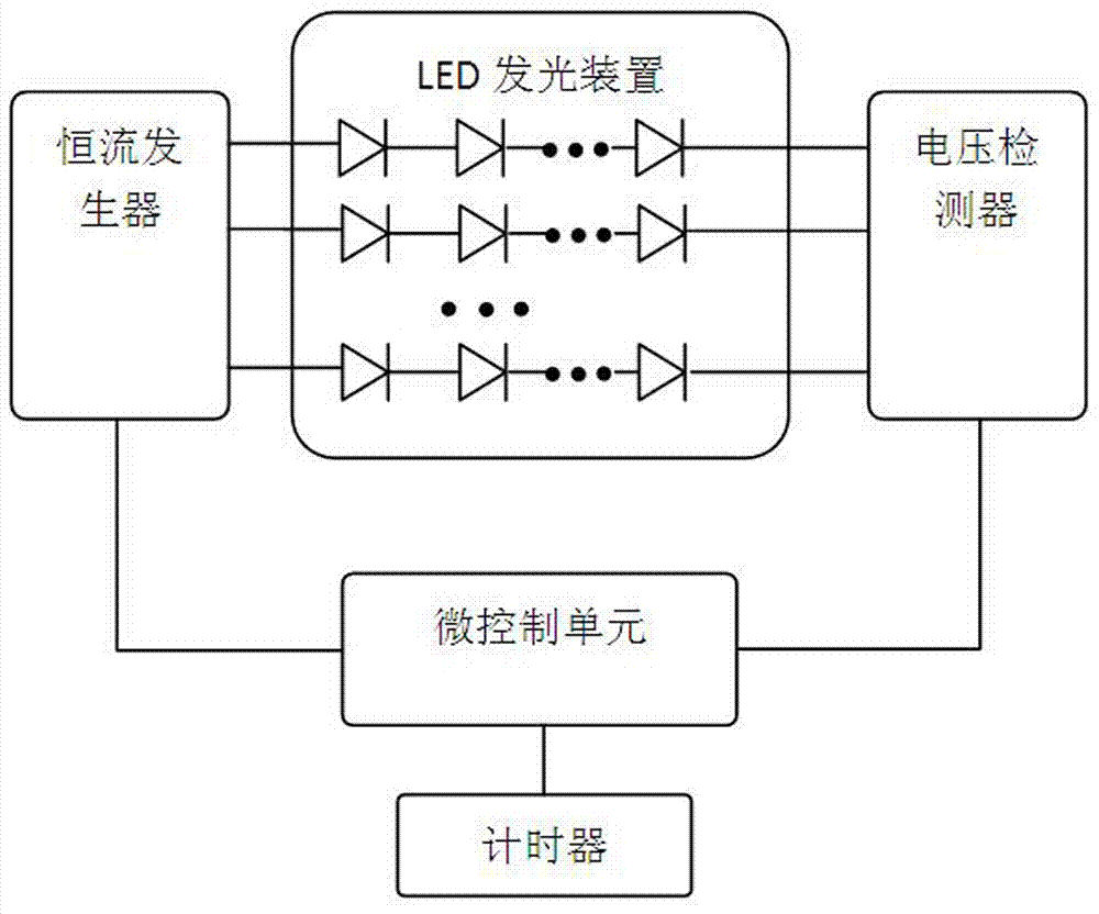
An LED light source with stable light color comprises an LED luminous device, a constant current generator, a micro-control unit, a voltage detector and a timer, wherein the micro-control unit is electrically connected with the constant current generator, the voltage detector and the timer, the constant current generator is electrically connected with an input end of the LED luminous device, the voltage detector is electrically connected with an output end of the LED luminous device, the micro-control unit is used for storing a change relation of brightness and color coordinates of each color of LED in the LED luminous device with a junction temperature and working time in advance and adjusting a duty ratio of each path of constant current output from the constant current generator after the change condition of the brightness and color coordinates of each color of LED is acquired by reading data of the voltage detector and the timer and calculating, so that hybrid light with stable color and brightness is emitted from the LED luminous device all the way. The LED light source is simple in structure and low in manufacturing cost, and the problem of change on the brightness and the chromaticity of the LED light source caused by reasons such as temperature change, current change and bead aging can be effectively solved.

Description

technical field [0001] The invention relates to the technical field of lighting, in particular to an LED light source with stable light color. Background technique [0002] With the development of semiconductor lighting, some specific application areas have put forward higher requirements for the stability of the brightness and chromaticity of LED light sources. However, during the actual use of the LED light source, due to temperature changes, current changes, lamp bead aging and other reasons, the stability of the luminosity and chromaticity of the LED is affected, and the light quality of the LED is reduced. LED light source with stable light color is suitable for high-end applications (such as LCD backlight, artistic lighting, medical lighting, etc.), and many research institutions at home and abroad have invested a lot of technical force. [0003] American Cree company adopts phosphor powder coating process technology, and by coating fluorescent method on multiple LED ...

Claims


Application Information

Patent Timeline
IPC IPC(8): H05B33/08H05B44/00
CPCH05B45/24H05B45/20H05B45/00
Inventor 许毅钦陈志涛古志良张志清许平
Owner GUANGDONG INST OF SEMICON IND TECH
Learn More