Winding no-bottom-wrinkle receiving mechanism

A technology without bottom wrinkle and mandrel, which is applied in winding strips, thin material handling, transportation and packaging, etc. It can solve the problems of bottom wrinkle caused by changing rolls and splicing materials, difficulty in meeting high-efficiency production, and slowing down of machine speed. , to achieve the effect of eliminating the curling of the base material end surface, reducing the curling phenomenon of the base material, and reducing the waste of finished products

Pending Publication Date: 2017-10-03
ZHONGSHAN SONGDE NEW MATERIAL EQUIP CO LTD
View PDF7 Cites 5 Cited by
  • Summary
  • Abstract
  • Description
  • Claims
  • Application Information

AI Technical Summary

Problems solved by technology

[0002] The existing film-type base material coating machine mainly has two mechanisms for rewinding and receiving materials: automatic material receiving or manual material receiving. The current automatic material receiving mechanism is easy to use, but due to the gap between the base material and the mandrel during the material receiving process Air is trapped between them, which often produces air bubbles; in addition, the end surface of the cut substrate is prone to curling, which leads to bottom wrinkles when changing rolls, that is, there is a long section of the substrate that has just started to be rolled. It cannot be used and can only be used for waste disposal; in order to reduce waste, some customers prefer to choose manual splicing, relying on the operator to cut the base material and wipe it by hand to eliminate the defects of bottom wrinkles; manual splicing mechanism, labor-intensive, It is also necessary to slow down the speed of the machine, which affects the production efficiency, and it is difficult to meet the needs of high-efficiency production; for this reason, the present invention provides a winding bottomless wrinkle automatic material receiving mechanism

Method used


Image

  • Winding no-bottom-wrinkle receiving mechanism

Examples


Embodiment Construction

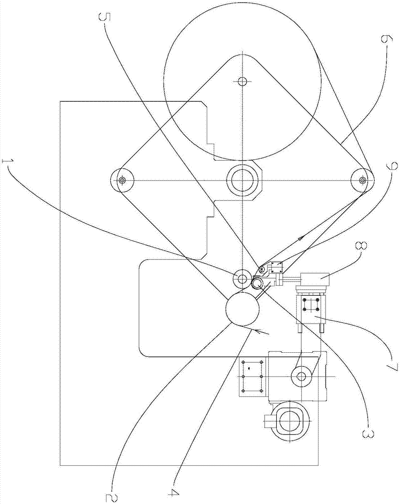
[0018] refer to figure 1 , the present invention is a winding bottomless wrinkle splicing mechanism, characterized in that it includes:

[0019] rotatable mandrel 1;

[0020] The mounting seat 2 is driven by a first driving device to be able to lift and move forward and backward;

[0021] The pressure roller 3 is rotatably installed on the mounting seat 2, and the substrate 4 passes between the pressure roller 3 and the mandrel 1;

[0022] The cutting knife 5 is driven by a second driving device to move along the width direction of the substrate 4 .

[0023] Along the traveling direction of the base material 4, the starting position of the pressure roller 3 is located at the back and upper side of the mandrel 1, and the pressure roller 3 has two kinds of moving trajectories, one of which is up and down (for bonding the base material 4 to the mandrel 1 above), the second is the arc track around the mandrel 1; in the present invention, the base material 4 is pasted on the man...


PUM


Abstract

The invention discloses a winding no-bottom-wrinkle receiving mechanism. The mechanism is characterized by comprising a rotatable mandrel, a mounting base driven to lift and move front and back through a first driving device, a pressing roller rotationally mounted on the mounting base, and a cutter driven to move in the width direction of a substrate through a second driving device, wherein the substrate passes between the pressing roller and the mandrel. The pressing roller moves up and down to bond the substrate on the mandrel; then, the substrate is cut off through movement of the cutter in the width direction of the substrate, so that the edge winding phenomenon of the substrate caused by a traditional automatic cutting mode can be greatly reduced; after the substrate is cut off, the first driving device drives the pressing roller to enable the pressing roller and the mandrel to extrude the substrate, and meanwhile, drives the pressing roller to act around the mandrel with an arc trajectory, so that the substrate can be preferably bonded on the roller surface of the mandrel to eliminate such defects as edge winding of the end surface of the substrate; and air between the mandrel and the substrate can be totally extruded out in the bonding process.

Description

technical field [0001] The invention relates to the field of winding of a coating machine, in particular to a winding bottomless wrinkle splicing mechanism. Background technique [0002] The existing film-type base material coating machine mainly has two mechanisms for rewinding and receiving materials: automatic material receiving or manual material receiving. The current automatic material receiving mechanism is easy to use, but due to the gap between the base material and the mandrel during the material receiving process Air is trapped between them, which often produces air bubbles; in addition, the end surface of the cut substrate is prone to curling, which leads to bottom wrinkles when changing rolls, that is, there is a long section of the substrate that has just started to be rolled. It cannot be used, and can only be used for waste disposal; in order to reduce waste, some customers prefer to choose manual splicing, relying on the operator to cut the base material and...

Claims


Application Information

Patent Timeline
Patent Type & Authority Applications(China)
IPC IPC(8): B65H19/26B65H19/28B65H19/30
CPCB65H19/26B65H19/28B65H19/30B65H2301/41818
Inventor 张晓玲郭晓春甘德韶谢起峰陈凡一
Owner ZHONGSHAN SONGDE NEW MATERIAL EQUIP CO LTD
Why Eureka
Try Eureka