Water resistor capable of self-cyclically flowing and cooling for industry

A circulating flow, water resistance technology, applied in resistors, liquid resistors, resistor parts and other directions, can solve the problem of reducing the operating efficiency of high-voltage pulse devices, unable to meet the requirements of long-term, continuous work, and the increase of water resistance temperature resistance changes. Large and other problems, to achieve the effect of good heat dissipation, simple structure and improved heat dissipation performance

Active Publication Date: 2017-10-03
四川弘博新材科技股份有限公司
View PDF18 Cites 4 Cited by
  • Summary
  • Abstract
  • Description
  • Claims
  • Application Information

AI Technical Summary

Problems solved by technology

[0010] The purpose of the present invention is to: for the existing water resistance, a radiator group is usually directly added outside the tube for heat exchange and heat dissipation, or the water resistance is connected to the water tank, the circulating water is introduced through the water pump, and the resistance liquid is realized by increasing the length of the pipeline. Heat dissipation, the heat dissipation speed of the resistance liquid is relatively slow. When it is working, the temperature of the water resistance and the resistance value of the air pressure may increase, which cannot meet the needs of long-term and continuous work, and reduces the corresponding high-voltage pulse. To solve the problem of device operation efficiency, provide an industrial self-circulating flow and cooling water resistance

Method used


Image

  • Water resistor capable of self-cyclically flowing and cooling for industry
  • Water resistor capable of self-cyclically flowing and cooling for industry
  • Water resistor capable of self-cyclically flowing and cooling for industry

Examples


Embodiment 1

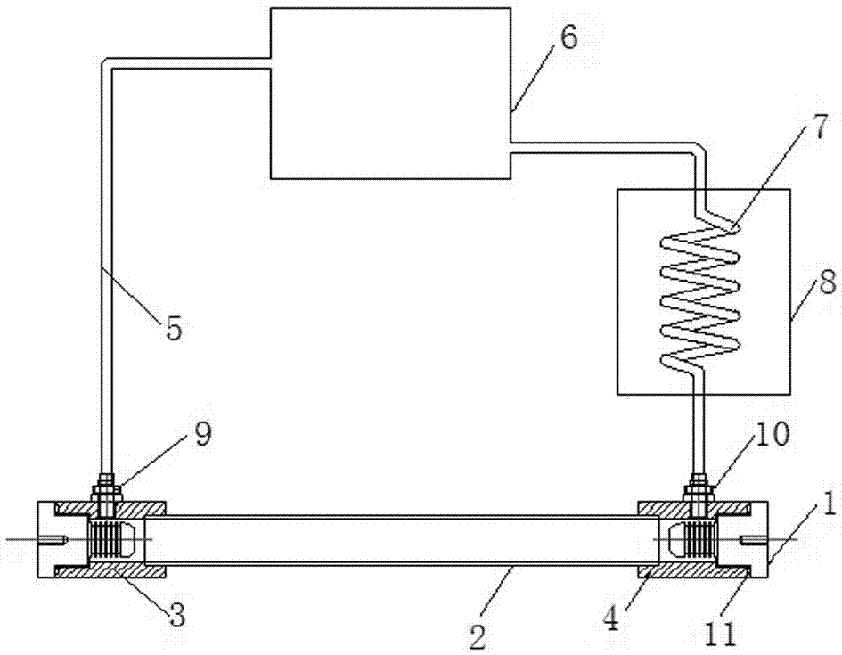
[0056] As shown in the figure, the water resistance of the present invention includes electrodes, water resistance main pipes, high-temperature connection end pipes, low-temperature connection end pipes, connection pipes, water tanks, spiral cooling pipes, and cooling devices arranged on the spiral cooling pipes. The electrodes are a group .

[0057] Electrodes, high-temperature connecting pipes, water resistor main pipes, low-temperature connecting pipes, and electrodes are connected in sequence to form a resistance main body, and the electrodes, high-temperature connecting pipes, water resistance main pipes, and low-temperature connecting pipes form a first accommodating chamber for distilled water . The main pipe of the water resistance and the high-temperature connection end pipe, and the main pipe of the water resistance and the low-temperature connection end pipe are connected by bonding. Sealing rings are respectively arranged between the high-temperature connection en...

Embodiment 2

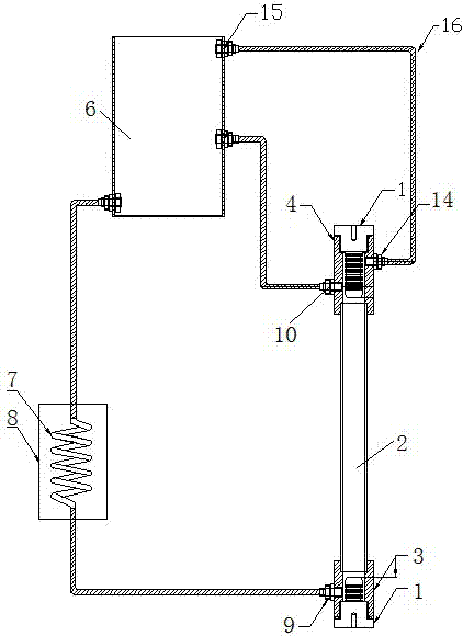
[0065] Such as figure 2 As shown, in this embodiment, the connecting pipes include a low-temperature water inlet pipe, a hot and cold water connecting pipe, a hot water compensation pipe, a first pipe joint, a low-temperature water inlet pipe, a cooling device, a cold and hot water connecting pipe, a water tank, and a hot water compensation pipe Connect with the second pipe joint in sequence. The main pipeline of the water resistor is arranged vertically, and the device also includes a pressure relief exhaust joint connected to the high-temperature connection end pipe, an exhaust connection pipe, a water vapor pipe outlet connection joint connected with the water tank, a pressure relief exhaust joint, an exhaust The connecting pipe and the outlet connector of the water vapor pipe are connected successively and the gas in the main pipeline of the water resistance can be discharged through the water tank through the pressure relief exhaust joint, the exhaust connecting pipe and...

Embodiment 3

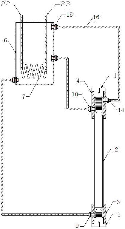
[0068] Such as image 3 , 4 As shown, in this embodiment, the cooling device is arranged in the water tank, the cooling pipe in the cooling device is cooled by cold air, and the two ends of the cooling pipe are respectively connected with the cold air inlet and the cold air outlet. The main pipe of the water resistance is arranged vertically, and the device also includes a pressure relief exhaust joint connected to the high-temperature connection end pipe, an exhaust connection pipe, a water vapor pipe outlet connection joint connected with the water tank, a pressure relief exhaust joint, an exhaust The connecting pipe and the outlet connector of the water vapor pipe are connected successively, and the gas in the main pipeline of the water resistance can be discharged through the water tank through the pressure relief exhaust joint, the exhaust connecting pipe, and the outlet connector of the water vapor pipe in sequence.

[0069] Others are the same as in Example 1.


PUM


Abstract

The invention discloses a water resistor capable of self-cyclically flowing and cooling for industry. The distilled water and other liquid resistor are used as the resistor, so that the resistance liquid can cyclically flow in the system in the premise of not using a water pump by using the effects of the temperature field, the gas pressure and the gravity; the heat produced in the working process is immediately taken away by the resistance liquid and cooled through an external condensation pipe, thereby improving the radiating performance; and meanwhile, since the overall system is an opening system, the resistance liquid is limited by the saturated vapor pressure under the atmosphere, the highest internal temperature of the water resistor is only the boiling point, and the pressure intensity is the environment pressure; the design of the opening system avoids the problem that the water resistor structure cannot be continuously used for a long time since the water resistor structure is damaged by the internal high temperature and high pressured caused by the insufficient radiation in the traditional closed water resistor, the performance of the service life of the water resistor are guaranteed, and the normal operation of the high-power pulse equipment under high-frequency and long-time condition is guaranteed.

Description

technical field [0001] The invention relates to the field of repetitive high-power pulses, in particular to a self-circulating flow and cooling water resistance. The invention utilizes the synergistic effect of temperature field, gravity and air pressure to ensure the stable flow of resistance liquid in the system, and effectively improve the heat dissipation performance of water resistance through the condensation tube, so that it can be maintained in a specific small temperature range to ensure its performance and The service life can effectively meet the normal operation of high-power pulse equipment under high-frequency and long-term conditions, and has a good application prospect. Background technique [0002] The water resistance has the advantages of good power tolerance and fast frequency response. It is suitable for making various shapes, and the resistance value is adjustable. It can be used as circuit matching or measuring components, etc., and can meet various hi...

Claims


Application Information

Patent Timeline
Patent Type & Authority Applications(China)
IPC IPC(8): H01C1/08H01C1/082H01C10/02
CPCH01C1/08H01C1/082H01C10/02
Inventor 殷柳付秀梅
Owner 四川弘博新材科技股份有限公司
Why Eureka
Try Eureka