Analog signal control circuit

An analog signal and control circuit technology, applied in the field of circuits, can solve the problems of instability, analog signal signal is easy to generate clutter signal frequency, etc., and achieve the effect of filtering clutter, great practical value and promotion value

Inactive Publication Date: 2017-10-03
XIDIAN UNIV
View PDF10 Cites 0 Cited by
  • Summary
  • Abstract
  • Description
  • Claims
  • Application Information

AI Technical Summary

Problems solved by technology

[0004] In view of the above situation, in order to overcome the defects of the prior art, the object of the present invention is to provide an analog signal control circuit, which has the characteristics of ingenious conception and humanized design, and effectively solves the problem that the transmission of analog signal signals is prone to clutter and signal Frequency instability problem

Method used


Image

  • Analog signal control circuit

Examples


Embodiment 1

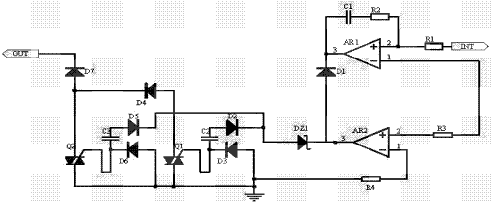
[0014] Embodiment 1, an analog signal control circuit, including a filter circuit and a rectifier circuit, the filter circuit is connected in series with an RC circuit to filter out medium and high frequency clutter, and at the same time uses an operational amplifier to stabilize the voltage and proportionally amplify the input to the rectifier circuit, and the rectifier circuit uses Thyristor and triac rectifier output stable analog signal;

[0015] The rectifier circuit uses the negative poles of the thyristors D2 and D5 to receive the analog signal of the filter circuit in two ways, and one way is connected in series with the capacitor C2, and the DC analog signal in the AC analog signal is filtered out by using the characteristic of the capacitor C2 to communicate with the traffic and block the DC, and the capacitor C2 The other end is connected to the negative pole of the thyristor D3 and the control pole of the triac Q1. The thyristor D3 plays the role of protecting the c...

Embodiment 2

[0016] Embodiment 2, on the basis of Embodiment 1, the filter circuit uses the comparison of the output signals of the operational amplifier AR1 and AR2 to output a stable analog signal to achieve the effect of filtering. The positive phase input terminal of the operational amplifier AR1 passes through the resistor R1 To receive the analog signal, the positive input terminal of the operational amplifier AR2 is connected to the inverting input terminal of the operational amplifier AR1, and the output signals of the operational amplifier AR1 and AR2 are superimposed, that is, the phase shift of the waveform of the analog signal, so that the clutter can be filtered out , the output stable waveform is an analog signal; the filter circuit includes a resistor R1, one end of the resistor R1 is an analog signal input port, the other end of the resistor R1 is connected to the non-inverting input of the resistor R2 op amp AR1, and the op amp AR1 The inverting input terminal is connected ...


PUM


Abstract

The invention discloses an analog signal control circuit comprising a filter circuit and a rectifier circuit, wherein the filter circuit is connected with an RC circuit in series to filter high frequency clutter and input the high frequency clutter to the rectifier circuit after voltage stabilization and scaling up of an operational amplifier, and the rectifier circuit outputs a stable analog signal by using a thyristor and a triode-thyristor rectifier; the cathodes of thyristors D2 and D5 receive the analog signal of the filter circuit in two paths, one path is connected with a capacitor C2 in series for filtering a DC analog signal in the AC analog signal by using the character of AC passing and DC isolating of the capacitor C2, wherein the thyristor D3 protects the circuit, the level of the control electrode of the triode-thyristor Q1 is too high to be reversely conducted and grounded, and if the level of the control electrode of the triode-thyristor Q1 is too low, the triode-thyristor Q1 is triggered and conducted, similarly, the same circuit connected in parallel achieves the rectifying effect through thyristors D5 and D6, a capacitor C3 and a triode-thyristor Q2, therefore the stabilization and filtering of the output analog signal of the high-voltage integrated circuit are effectively solved, and the abnormal analog signal can be effectively regulated and controlled.

Description

technical field [0001] The invention relates to the technical field of circuits, in particular to an analog signal control circuit. Background technique [0002] At present, the transmission of analog signals is prone to clutter, and the signal frequency is unstable. Now, to solve this problem, a controller with a chip as the core is used for processing, and the control is stable, but the structure is complicated. Because the chip is used as the core processor , maintenance is difficult, the equipment is easily damaged, and its functional effect depends on the quality of the chip, resulting in high cost and serious waste of resources. [0003] So the present invention provides a new solution to solve this problem. Contents of the invention [0004] In view of the above situation, in order to overcome the defects of the prior art, the object of the present invention is to provide an analog signal control circuit, which has the characteristics of ingenious conception and hu...

Claims


Application Information

Patent Timeline
IPC IPC(8): H03H11/46
CPCH03H11/46
Inventor 李迪费春龙杨银堂周歧发柴常春李娅妮
Owner XIDIAN UNIV
Why Eureka
Try Eureka