Novel gearbox capable of transmitting large torque

A gearbox and high-torque technology, which is applied in the field of new gearboxes, can solve problems such as the inability to operate work tools, the steel belt is easy to slip, and the inability to transmit large torques, etc., achieving high practical value and promotion value, and saving labor.

Inactive Publication Date: 2017-06-09
YANCHENG PINGAN MACHINERY
View PDF0 Cites 0 Cited by
  • Summary
  • Abstract
  • Description
  • Claims
  • Application Information

AI Technical Summary

Problems solved by technology

[0002] The existing automatic transmissions AT and CVT both have their own advantages and disadvantages. AT is actually a transmission with an improved manual structure for automatic shifting. Its working principle is that the gears slide on the spline shaft, and they are axially engaged. , using synchronous gear adjustment to remove the disadvantages of tooth beating and abnormal noise, but due to the structural characteristics of synchronous gears, large torque cannot be transmitted; while CVT does not use gears to change speed ratios, and uses steel belts to transmit power. By changing the driving wheel and passive The diameter of the wheel changes, and the steel belt is easy to slip. Both are only suitable for small passenger cars, so they cannot be used in medium-sized, heavy-duty cars or even cars with a slightly larger displacement. Especially, most of the gearboxes with improved construction machinery structures are manual Gear shift or power shift, and it does not have ten forward gears and ten reverse gears, so in actual operation, it is impossible to realize the operation of the working tool turning the head in a small space, and it cannot meet the needs of practical applications

Method used


Image

  • Novel gearbox capable of transmitting large torque
  • Novel gearbox capable of transmitting large torque
  • Novel gearbox capable of transmitting large torque

Examples


Embodiment Construction

[0018] The present invention will be further described in detail below in conjunction with the accompanying drawings and specific embodiments.

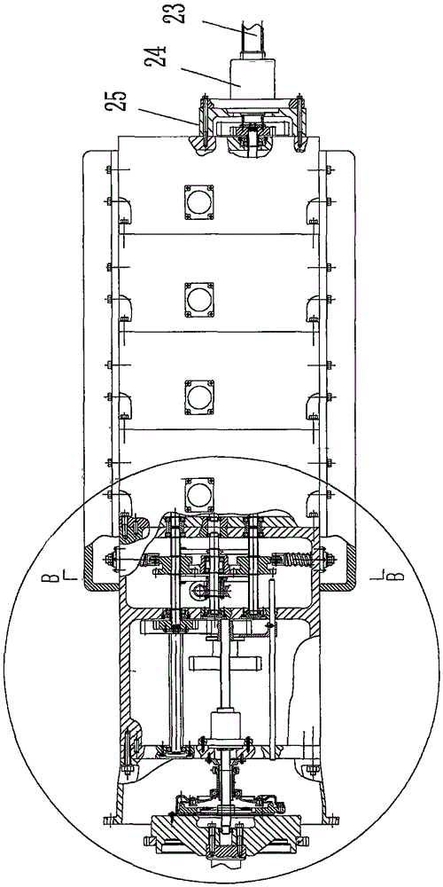
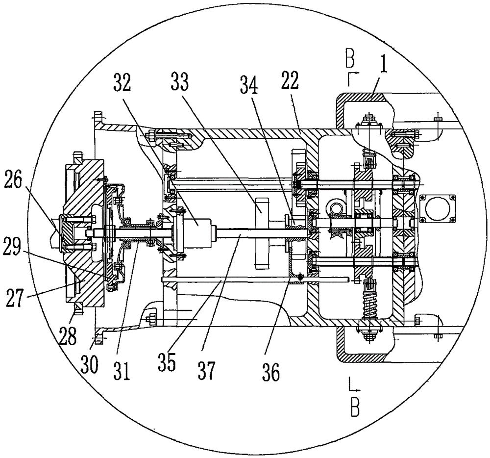
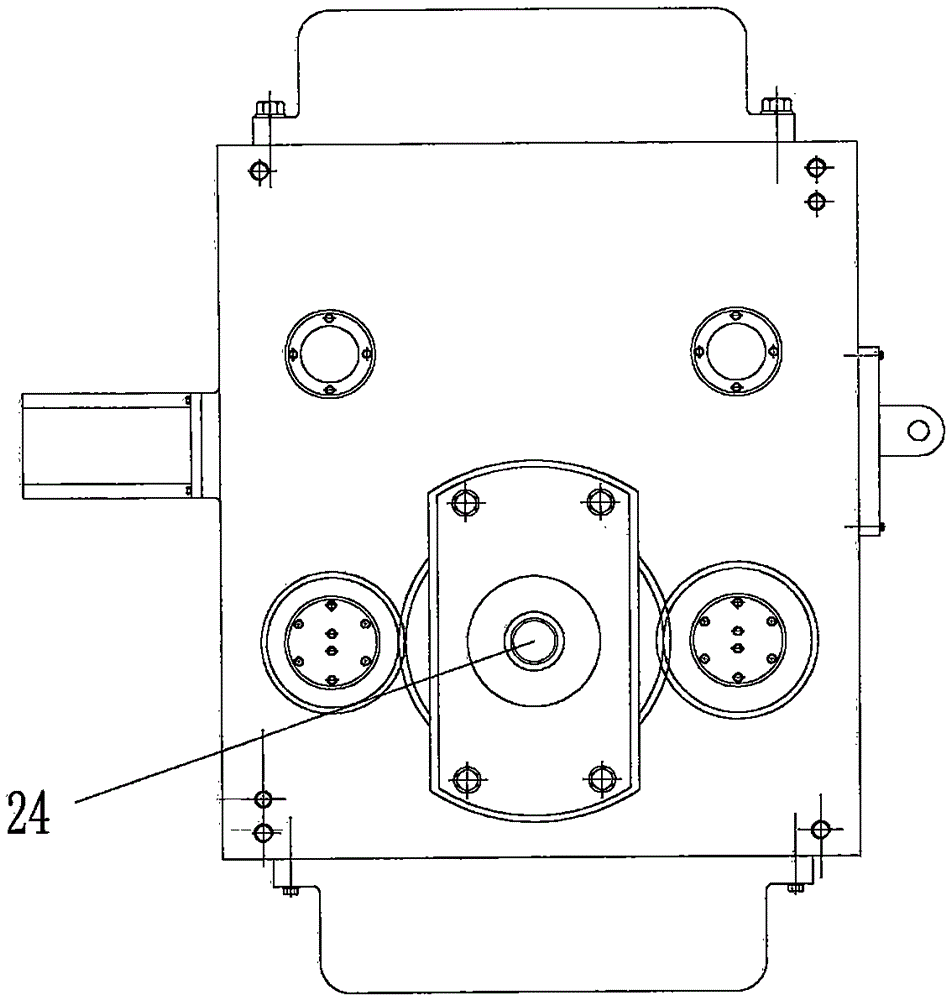
[0019] as attached Figure 1-7The shown novel gearbox of the present invention that can transmit high torque includes a box body 1, a power output shaft 23, a first bracket 25, an output shaft speed and torque sensor 24, a servo motor 3, a transmission mechanism, a first A box 22, connecting box 30, engine crankshaft 26, input shaft 37, engine flywheel 27, flywheel ring gear 28, clutch assembly 29, clutch separation mechanism 31, input shaft speed and torque sensor 32, exchange gear 34, reverse gear 33, shift fork shaft 35 and shift fork 36; said casing 1 side is provided with power output shaft 23; said power output shaft 23 is provided with output shaft speed and torque sensor 24 on the first bracket 25 ; The box 1 is provided with five servo motors 3 arranged in sequence; the servo motor 3 is connected to the corresponding transmi...


PUM


Abstract

The invention relates to a new type of gearbox capable of transmitting large torque. A power output shaft is arranged on one side of the box body; an output shaft speed and torque sensor located on the first bracket is arranged on the power output shaft; The five servo motors; the servo motor is connected with the corresponding transmission mechanism; the other side of the box is connected with the connection box through the first box; the engine crankshaft is connected with the input shaft in the first box; Flywheel and flywheel ring gear; clutch assembly and clutch separation mechanism are provided on the input shaft; input shaft speed and torque sensors are arranged on the input shaft; one end of the input shaft is connected with the exchange gear; both ends of the exchange gear are respectively connected with the reverse gear and the transmission The mechanism is connected; the exchange gear is connected with the shift fork arranged on the shift fork shaft. The new gearbox of the present invention that can transmit large torque has ten forward gears and reverse gears, which solves the problem of turning around with working tools in a narrow space.

Description

technical field [0001] The invention relates to a gearbox, in particular to a novel gearbox capable of transmitting high torque. Background technique [0002] The existing automatic transmissions AT and CVT both have their own advantages and disadvantages. AT is actually a transmission with an improved manual structure for automatic shifting. Its working principle is that the gears slide on the spline shaft, and they are axially engaged. , using synchronous gear adjustment to remove the disadvantages of tooth beating and abnormal noise, but due to the structural characteristics of synchronous gears, large torque cannot be transmitted; while CVT does not use gears to change speed ratios, and uses steel belts to transmit power. By changing the driving wheel and passive The diameter of the wheel changes, and the steel belt is easy to slip. Both are only suitable for small passenger cars, so they cannot be used in medium-sized, heavy-duty cars or even cars with a slightly larger...

Claims


Application Information

Patent Timeline
IPC IPC(8): F16H57/023F16H63/32
CPCF16H57/023F16H63/32F16H2200/0069F16H2200/0082F16H2306/00
Inventor 王建平
Owner YANCHENG PINGAN MACHINERY
Why Eureka
Try Eureka